Safety device for pinching zone of elevator doors

Active Publication Date: 2006-05-16
CEDES AG
View PDF19 Cites 21 Cited by
  • Summary
  • Abstract
  • Description
  • Claims
  • Application Information

AI Technical Summary

Benefits of technology

[0008]It is therefore an object of the present invention to remove the disadvantages of the elevator systems of the prior art. It is intended to create the prerequisites for making elevator systems with automatically operable sliding doors safe in such a way that a risk of injuries to the public has been removed to a great extent, even when using sliding glass doors. In the course of this it is intended to prevent objects from being pinched at the pinching edges of sliding doors, or people from sustaining injuries to their limbs, in particular their hands, because they are taken along by the opening sliding door and pinched. In the course of this, the normal operation of the sliding door should not be disturbed, and an unintentional or also intentional triggering of the safety mechanism in particular should be prevented. The safety mechanism should be suitable for simple retroactive installation. Unintentional or intentional damage to the safety mechanism should be prevented, and acts of vandalism should not be provoked at all.

Problems solved by technology

The problematic area with automatically opening sliding doors lies in particular at the pinching edge between the surface of the door panel and the door jamb.
The sliding doors of known elevator systems pose a definite risk that an object leaning against the sliding door, or even a part of a body of a person leaning against the sliding door, will be taken along by the automatically opening sliding door and be pinched.
But the coefficient of friction between glass and the skin is relatively large.
This can lead to injury when it is attempted to release the hand.
A difficulty in the conversion of a system with a number of presence sensors lies, for example, in routing the signal of the elevator shaft door in front of which the elevator car is stopped to the elevator car so that, when required, the door opening mechanism can be changed to a slow opening mode or interrupted.
Additional problems are posed by the logical linkage of the presence sensors, so that a correct operation of the elevator system is preserved.

Method used


Image

  • Safety device for pinching zone of elevator doors
  • Safety device for pinching zone of elevator doors
  • Safety device for pinching zone of elevator doors

Examples


Embodiment Construction

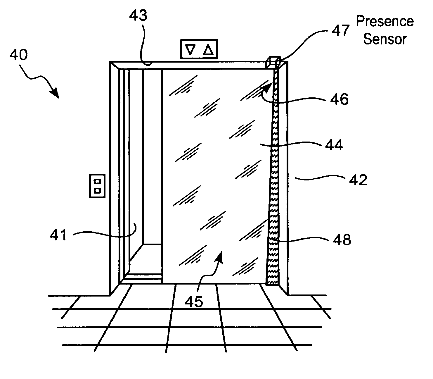
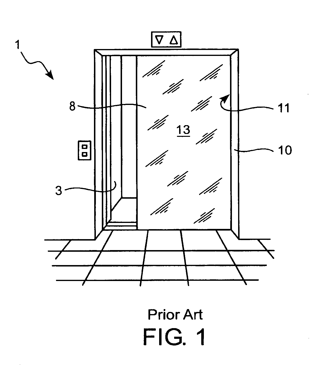
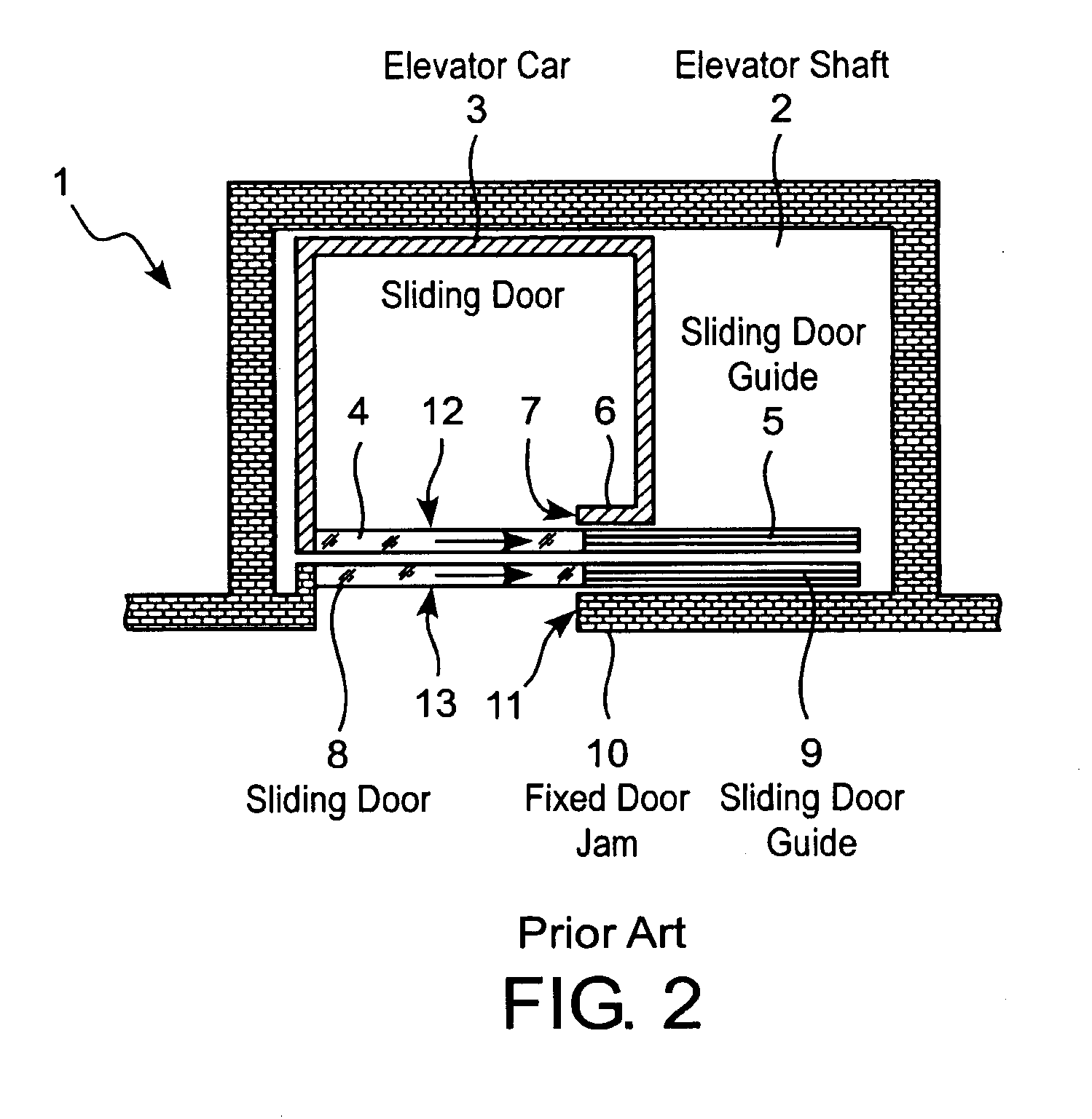
[0035]In FIGS. 1 and 2, an elevator system as a whole is identified by the reference numeral 1. It comprises an elevator shaft 2 and an elevator car 3, whose position in the elevator shaft can be changed. The elevator car 3 is moved by means of a motor in a known manner. Sliding doors 8, or 4, which are automatically operable, are respectively provided at the entrances to the elevator shaft 2 and the elevator car 3. Customarily the sliding doors 4, 8 can only be actuated together. In this case, the sliding door 4 of the elevator car 3 is an actively operable door, which is driven by a motor usually arranged on the roof of the elevator car 3. The sliding door 8 at the elevator shaft is a purely passive door, which can be operated by means of engagement elements on the sliding door 4 of the elevator car 3. The sliding doors 8, or 4, slide in sliding door guides, which are indicated by the reference numerals 9, or 5, in FIG. 2. The sliding doors 8, or 4, can be displaced in relation to...


PUM


Abstract

The described safety mechanism is embodied for elevator systems with an elevator car, which can be displaced in an elevator shaft. The entrances to the elevator shaft and to the elevator car each have at least one sliding door, which is automatically operable by a drive mechanism, preferably arranged on the elevator car. At least one detector device is provided at each sliding door, which is placed in the area of a pinching edge between a sliding door and a door jamb, and / or between two adjoining sliding door panels. Depending on the detected state of the monitored areas, the detector device generates a door release signal, or provides the interruption of the drive mechanism for opening the sliding door. The signals from the detector devices at the sliding doors of the elevator shaft can be received as a function of the position of the elevator car. In this case only the signals from the detector device from the sliding door of the elevator shaft can be considered, which is to be automatically opened next, together with the sliding door of the elevator car.

Description

RELATED APPLICATIONS[0001]This application claims priority under 35 U.S.C. §§119 to Swiss Application 2000 1162 / 00 filed in Switzerland on Jun. 13, 2000, and under 35 U.S.C. §120 to PCT / CH01 / 00352 filed as an International Application on Jun. 7, 2001, and designating the United States, the entire contents of which are hereby incorporated by reference in their entireties.BACKGROUND[0002]1. Field of the Invention[0003]The invention relates to a safety mechanism for elevator systems. The invention also relates to a method for operating the safety mechanism in accordance with the invention.[0004]2. Background Information[0005]The elevator cars, as well as the elevator shaft of elevator systems which meet modern safety requirements are customarily provided with automatically operable sliding doors. Depending on the size of the door opening, these can be single- or multi-panel individual sliding doors, or centrally opening double sliding doors. In various elevator systems, the different d...

Claims


Application Information

Patent Timeline
IPC IPC(8): B66B13/14B66B13/26E05F15/00
CPCB66B13/26E05Y2400/66E05F2015/435E05Y2900/104E05F15/43E05Y2600/46
Inventor DE COI, BEAT
Owner CEDES AG
Why Eureka
Try Eureka