Bar seal for shipping container

a bar seal and shipping container technology, applied in the field of security systems, to achieve the effect of retaining its effectiveness and being easy to manufacture and maintain

Inactive Publication Date: 2006-05-16
MORENO JOSE M
View PDF4 Cites 39 Cited by
  • Summary
  • Abstract
  • Description
  • Claims
  • Application Information

AI Technical Summary

Benefits of technology

[0014]It is one of the main objects of the present invention to provide a bar seal for shipping containers that is effective against tampering.
[0015]It is another object of this invention to provide a ba

Problems solved by technology

Applicant, however, is not aware of any bar seal that includes a single-use security bar seal system comprising iden

Method used


Image

  • Bar seal for shipping container
  • Bar seal for shipping container
  • Bar seal for shipping container

Examples


Embodiment Construction

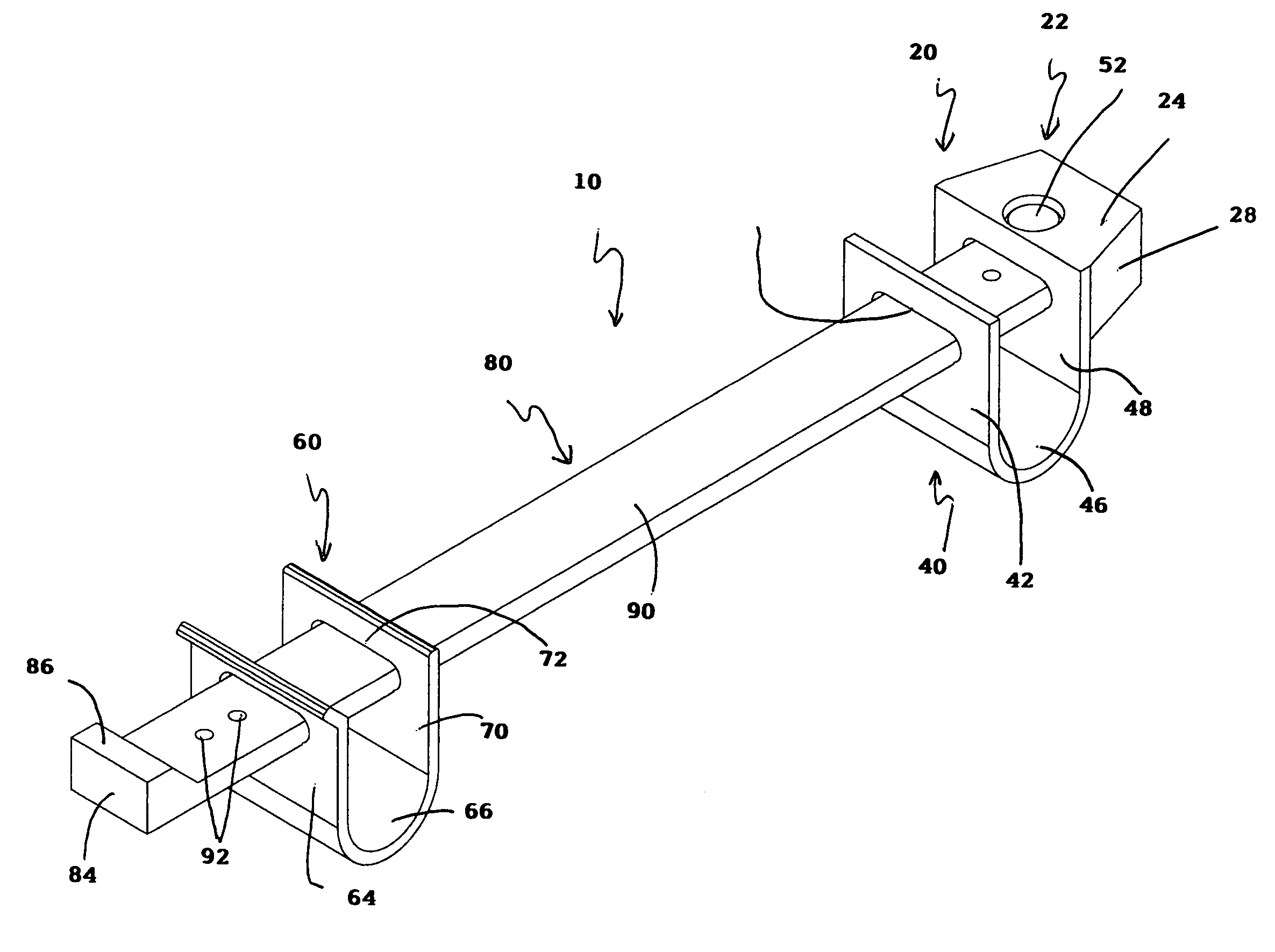
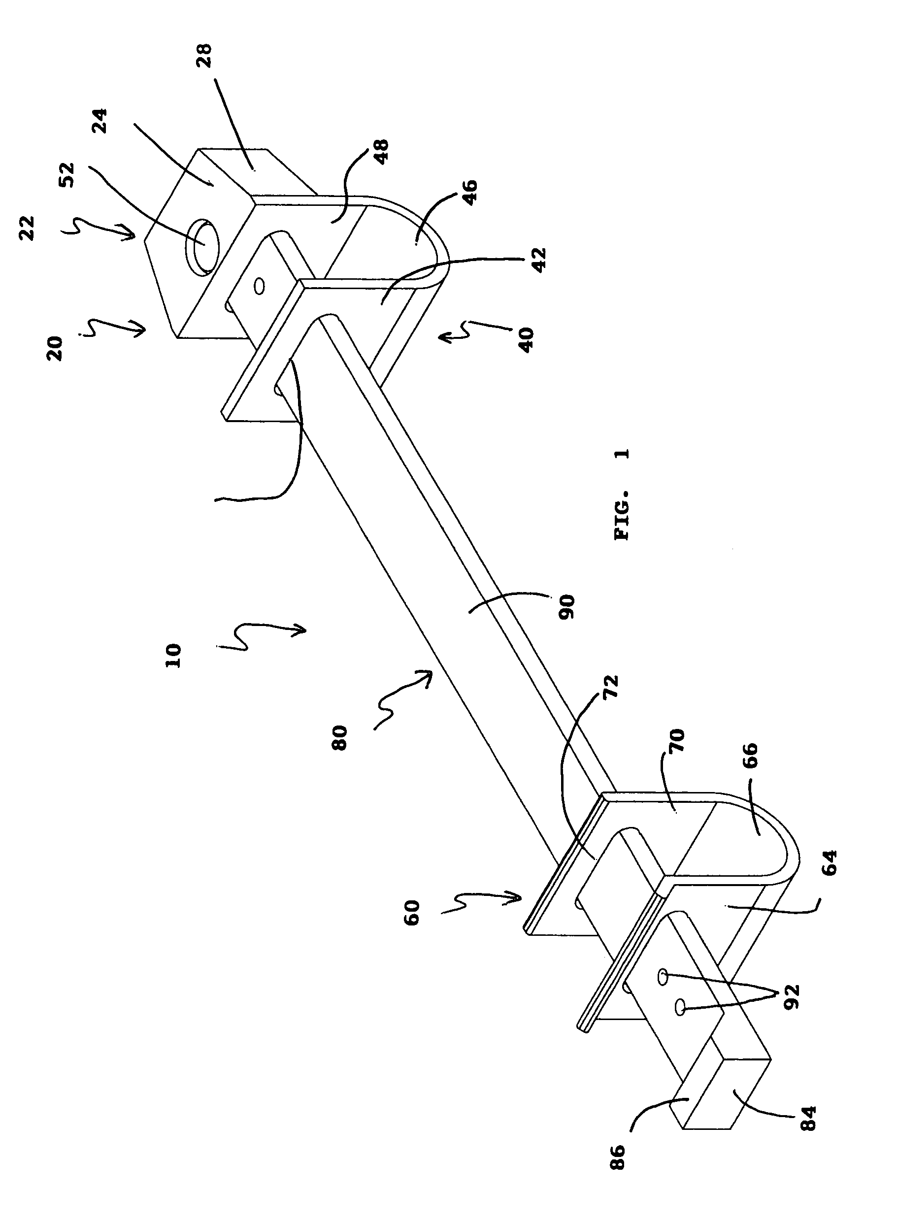
[0032]Referring now to the drawings, where the present invention is generally referred to with numeral 10, it can be observed that it basically includes receiving bracket 20, support assembly 60, and bar member 80.

[0033]As seen in FIG. 1, the instant invention comprises receiving bracket 20 and support assembly 60 locking bar member 80, whereby receiving bracket 20 and support assembly 60 have slots of cooperative characteristics to receive bar member 80 therethrough.

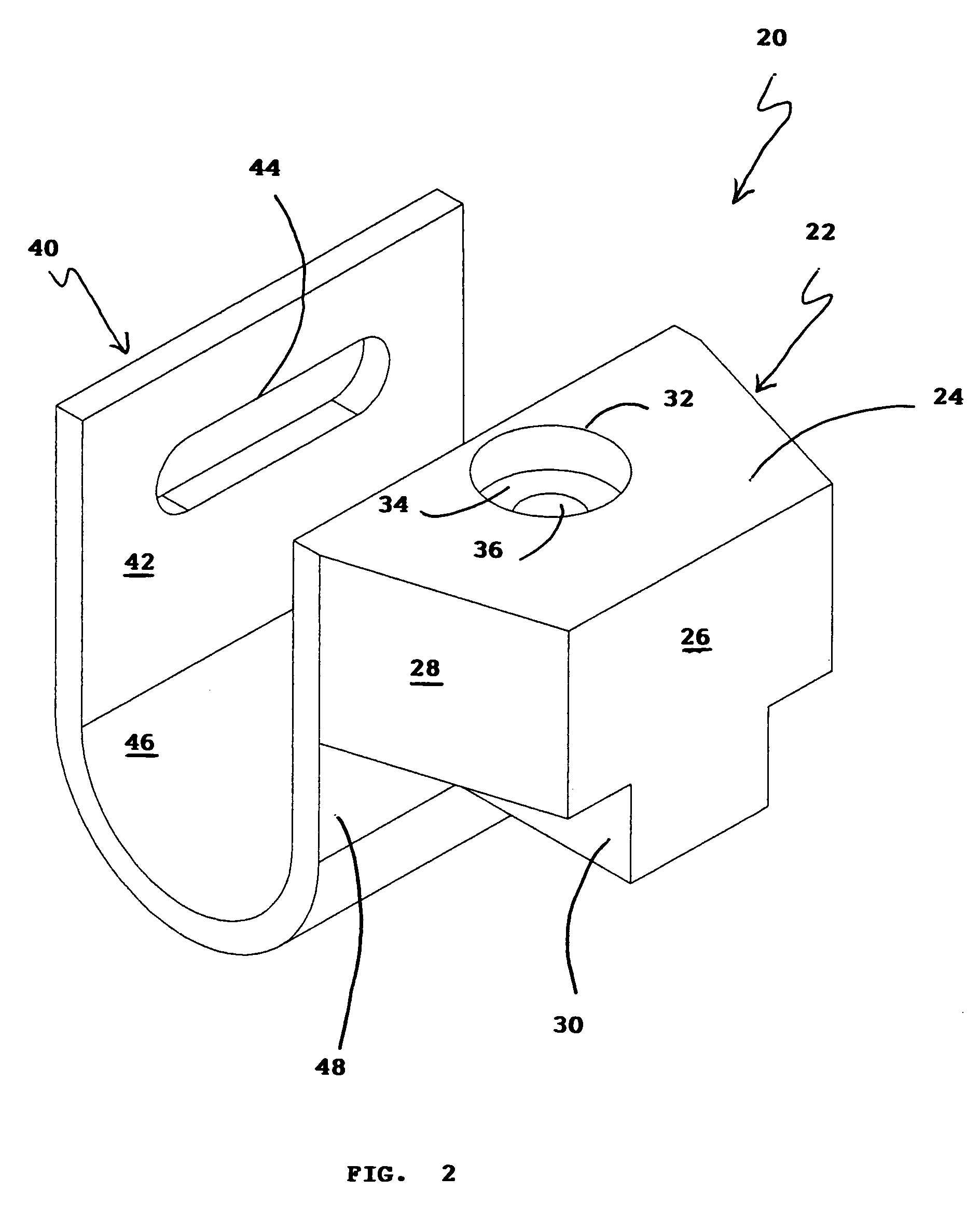
[0034]As best seen in FIGS. 2 and 3, receiving bracket 20 comprises receiving assembly 22 and support 40. Receiving assembly 22 comprises wall 24 having aperture 32 to receive pin 50. Within aperture 32 is face 34, and aperture 36 of a smaller diameter than aperture 32 to receive shank 54, seen in FIG. 3a. Perpendicularly from face 24 are walls 26, 28, and 30, which form receiving assembly 22. It is noted that the walls opposite from walls 28 and 30, not seen, are a mirror image of walls 28 and 30.

[0035]Support 40 is co...


PUM


Abstract

A single-use security bar seal assembly for shipping containers, comprising an elongated bar member having first and second ends, a support assembly, and a receiving bracket. The single-use security bar seal assembly has matching identification codes on all individual parts and electrical means for determining severance of the elongated bar member.

Description

BACKGROUND OF THE INVENTION[0001]1. Field of the Invention[0002]The present invention relates to security systems and more particularly, to security bar seals for shipping containers.[0003]2. Description of the Related Art[0004]Millions of shipping containers flow through ports all over the world on a daily basis. It is imperative to keep the contents of those shipping containers secure and not have them compromised. In addition to theft of contents, there is a need to ensure that shipping containers are not used as vehicles to transport illegal narcotics, illegal weapons, and otherwise unauthorized matter.[0005]Several designs for bar seals have been designed in the past. Applicant, however, is not aware of any bar seal that includes a single-use security bar seal system comprising identification matching codes on all individual parts and electrical means for determining severance of the bar assembly.SUMMARY OF THE INVENTION[0006]A single-use security bar seal assembly for shipping...

Claims


Application Information

Patent Timeline
IPC IPC(8): E05C19/00E05C21/02E05C19/18
CPCB65D90/008B65D90/22G09F3/0329E05C19/186G09F3/0317E05B39/02B65D2211/00E05B83/02Y10T70/40Y10T292/23Y10T292/331
Inventor MORENO, JOSE M.
Owner MORENO JOSE M
Why Eureka
Try Eureka