Method of grounding shielded wire and structure for grounding shielded wire

a shielded wire and shield layer technology, applied in the direction of connection contact material, connection device connection, basic electric elements, etc., can solve the problems of large load on shielded wire and core wire, damage to shield layer, etc., and achieve high-quality shielded wire. the effect of enhancing workability and noise shield performan

Active Publication Date: 2006-05-16
YAZAKI CORP
View PDF8 Cites 59 Cited by
  • Summary
  • Abstract
  • Description
  • Claims
  • Application Information

AI Technical Summary

Benefits of technology

[0021]According to this configuration, the core wire of the attached wire can be electrically connected to the ring portion only by passing through the through holes of the sleeve fitting. Therefore, the core wire of the attached wire can be reliably connected to the ring portion, without causing the core wire of the attached wire

Problems solved by technology

Accordingly, the braided wire and core wire may be subjected to a large load to be damaged.
Further, in JP H10

Method used


Image

  • Method of grounding shielded wire and structure for grounding shielded wire
  • Method of grounding shielded wire and structure for grounding shielded wire
  • Method of grounding shielded wire and structure for grounding shielded wire

Examples


first embodiment

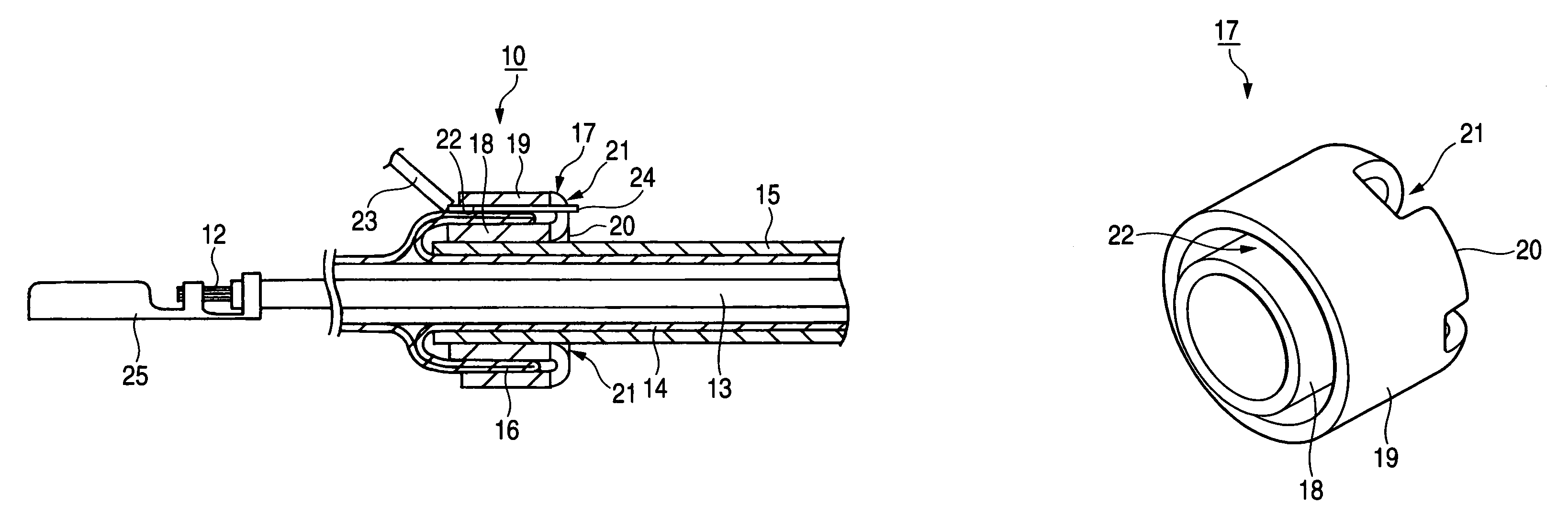
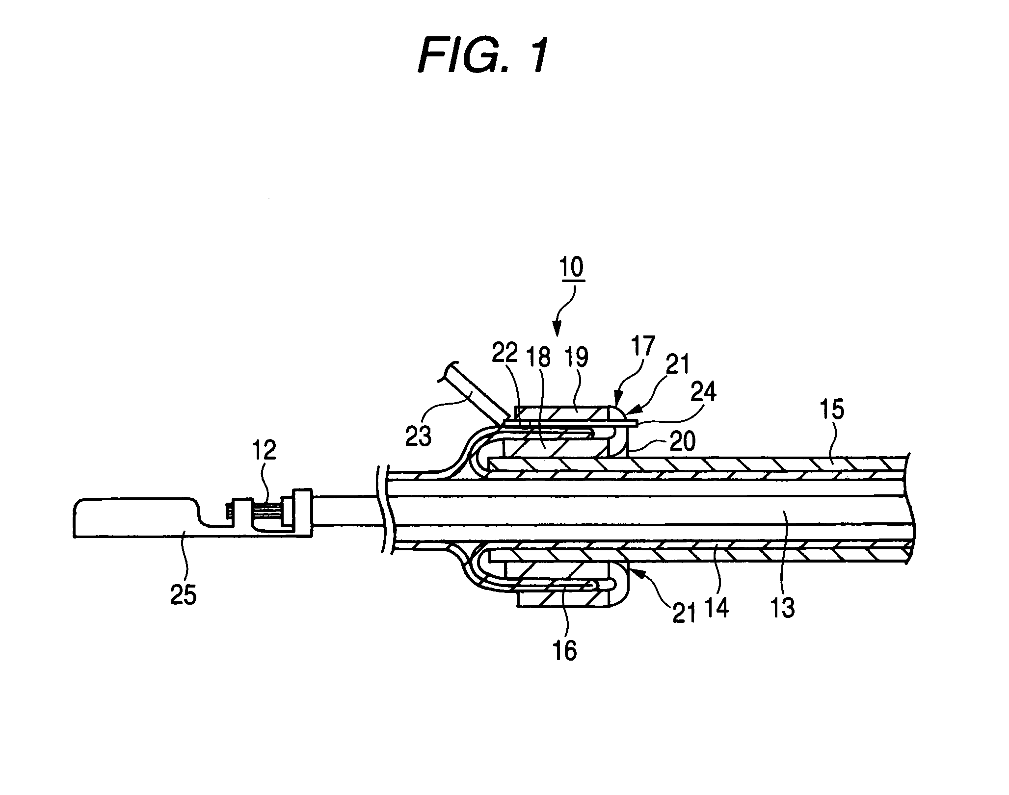
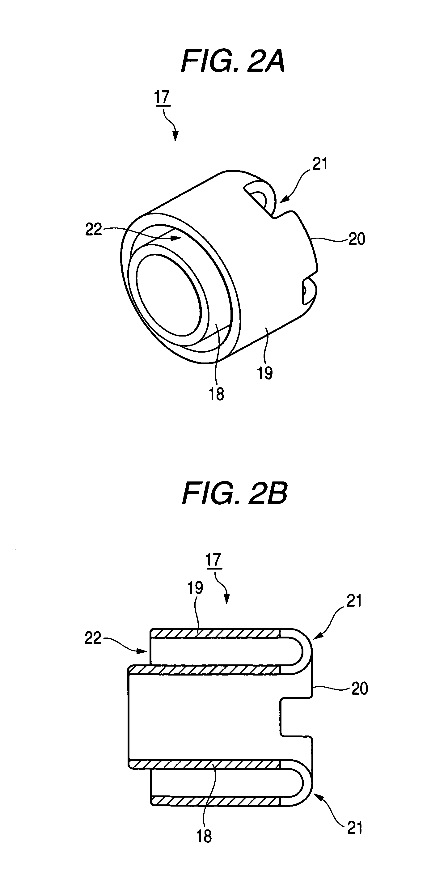
[0031]FIG. 1 is a cross-sectional view of a shielded wire which is manufactured using a first embodiment of a method of grounding a shielded wire and a structure for grounding a shielded wire according to the present invention. FIGS. 2A and 2B show a sleeve fitting which is used in the method of grounding a shielded wire shown in FIG. 1. FIG. 2A is an external perspective view of the sleeve fitting, and FIG. 2B is a cross-sectional view of the sleeve fitting. FIG. 3 is a cross-sectional view of the shielded wire shown in FIG. 1. FIG. 4 is a cross-sectional view before the shielded wire shown in FIG. 1 is grounded. FIG. 5 is a cross-sectional view of a modification of the shielded wire shown in FIG. 1.

[0032]As shown in FIG. 1, a shielded wire 10, which is manufactured using a method of grounding a shielded wire and a structure for grounding a shielded wire according to the present invention, has a core wire 12 made of a conductor, an insulating inner sheath 13 that covers the core wi...

second embodiment

[0047]Next, a second embodiment of a method of grounding a shielded wire and a structure for grounding a shielded wire according to the present invention will be described with reference to FIG. 6. Moreover, in FIG. 6, the same parts as those in the shielded wire 10 described above are represented by the same or corresponding reference numerals, and thus the descriptions thereof will be simplified or omitted.

[0048]FIG. 6 is a cross-sectional view of a shielded wire manufactured using the second embodiment of the method of grounding a shielded wire and a structure for grounding a shielded wire according to the present invention.

[0049]As shown in FIG. 6, a sleeve fitting 30 that is used in the method of grounding a shielded wire according to the second embodiment of the present invention is attached in an opposite direction to the first embodiment. For this reason, a ring portion 16 of a braided wire 14 is led to an opposite side to an insulating outer sheath 15 so as to be separated ...


PUM


Abstract

In a method of grounding a shielded wire and a structure of grounding a shielded wire, a ring portion is formed in a ring shape by leading a braided wire to or to an opposite side of an insulating outer sheath so as to be separated in an outer circumferential direction of the insulating outer sheath. With respect to an outer circumference of the insulating outer sheath, an inner circumferential cylinder is disposed at an inner circumference side of the ring portion and an outer circumferential cylinder is disposed at an outer circumference side thereof. Further, the outer circumferential cylinder and the inner circumferential cylinder are connected each other to form a sleeve fitting. With the sleeve fitting, an attached wire is connected to the ring portion, such that grounding is performed.

Description

BACKGROUND OF THE INVENTION[0001]1. Field of the Invention[0002]The present invention relates to a method of grounding a shielded wire that grounds a braided wire in a terminal of the shielded wire, and to a structure of grounding a shielded wire.[0003]2. Related Art[0004]As an example of a method of grounding a shielded wire according to the related art, a method has been known in which, in a state one side of a shield terminal is placed on an insulating outer sheath and simultaneously a resin chip overlaps on one side of the shield terminal, ultrasonic vibration is applied to fuse and scatter at least the insulating outer sheath, thereby forming a shield conducting portion through which one side of the shield terminal comes into conductive contact with a braided wire is formed (for example, see Japanese Patent Publication No. JP H11-135167A).[0005]Further, as another example of a method of grounding a shielded wire according to the related art, a method has been known in which a s...

Claims


Application Information

Patent Timeline
IPC IPC(8): H01R13/648H01R4/22H01R4/64
CPCH01R9/032H01R13/648H01R9/0512H01R9/0518H01R13/65912
Inventor ASAKURA, NOBUYUKISAKAGUCHI, TADAHISA
Owner YAZAKI CORP
Why Eureka
Try Eureka