Dialysis device

a technology of dialysis device and dialysis concentrate, which is applied in the direction of filtration separation, multi-stage water/sewage treatment, and separation processes, etc., can solve the problems of dialysis concentrate solution diluted, water flown into the pump may leak into the metering chamber, and the adhesion between the cylinder and the piston, so as to prevent the leakage of clean water out of the piston pump, prevent the impairment of sliding performance, and high accuracy

Active Publication Date: 2006-05-16
SHIBUYA IND CO LTD
View PDF3 Cites 16 Cited by
  • Summary
  • Abstract
  • Description
  • Claims
  • Application Information

AI Technical Summary

Benefits of technology

[0006]In view of the above described problems, the invention provides a dialysis device that prevents impairment of sliding performance between sliding portions of a piston and a cylinder of a piston pump, and prevents a leak of water from the sliding portions caused by water supply pressure.
[0011]According to the invention, the clean water from the water supply passage is flown through the gap between the piston and the cylinder to wash off the used dialysis solution having flown into the gap between the piston and the cylinder when the piston pump is the extraction pump, and to prevent drying of the dialysis concentrate solution having flown into the gap between the piston and the cylinder when the piston pump is the concentrate solution pump, thereby preventing impairment of sliding performance between the piston and the cylinder.
[0012]Further, the open / close valve is intermittently opened, and thus water supply pressure of the clean water having flown into the inflow port intermittently acts between the cylinder and the piston. This prevents a leak of the clean water into a metering chamber of the piston pump to keep the amounts of dialysis solution and concentrate solution with high accuracy, and prevents a leak of the clean water out of the piston pump.

Problems solved by technology

It is known that when a dialysis solution is fed by a piston pump, a deposition from the dialysis solution may cause adhesion between a cylinder and a piston.
However, as disclosed in Patent Document 1, when the supply line of water is simply connected to the washing ports of the piston pump for flowing water into the pump, water supply pressure from a water supply source to the supply line always acts between the cylinder and the piston of the piston pump, and the water having flown into the pump may leak into a metering chamber that sucks a dialysis solution in the cylinder or out of the piston pump.
Further, if such a piston pump is used as a concentrate solution pump for dispensing a dialysis concentrate solution, water leaking into the metering chamber may dilute the dialysis concentrate solution.

Method used


Image

  • Dialysis device
  • Dialysis device
  • Dialysis device

Examples


first embodiment

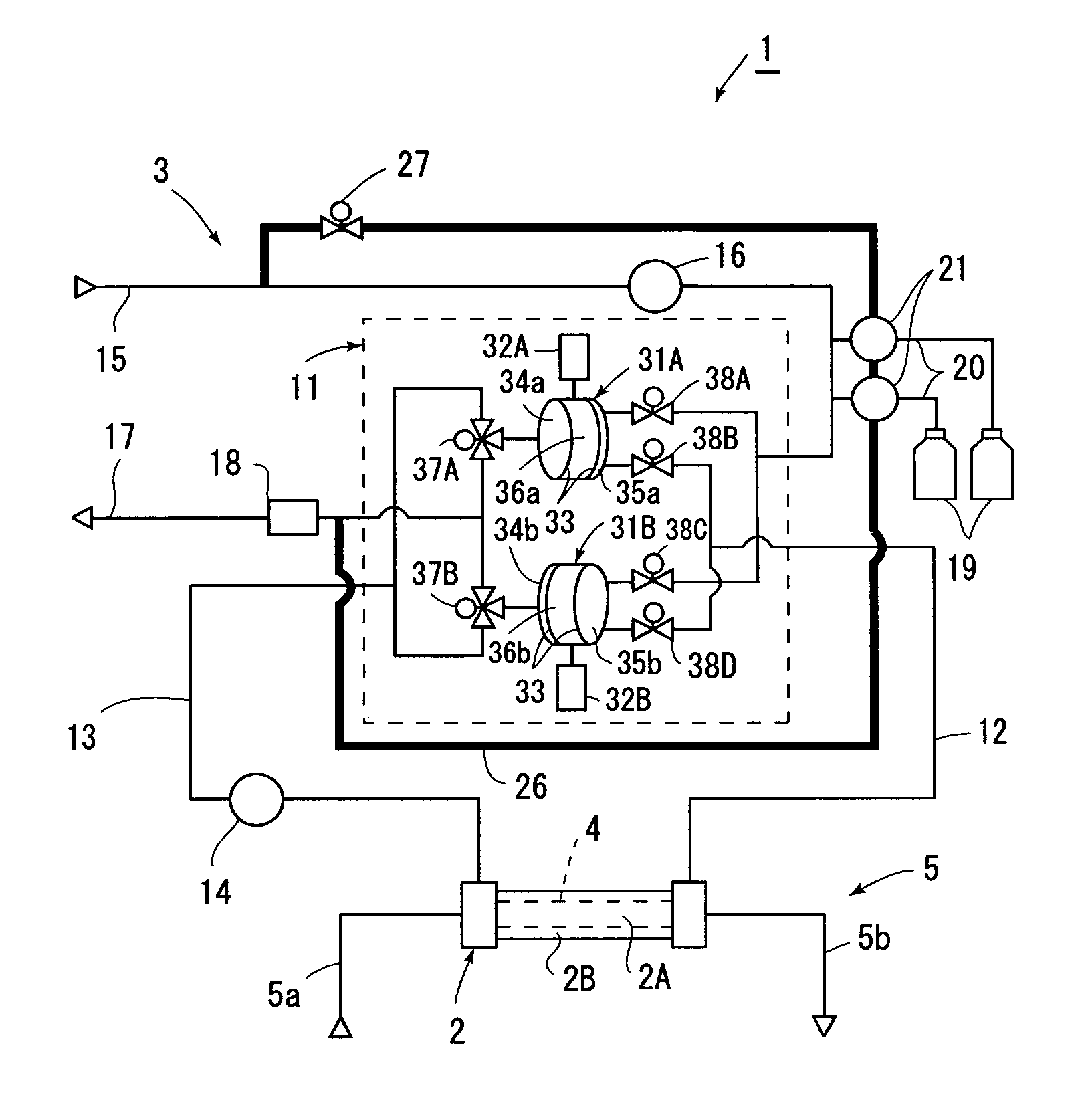
[0069]The dialysis device 101 is a single-patient-use dialysis device like the dialysis device 1 includes a dialyser 102, and a dialysis solution circuit 103 and a blood circuit 105 connected to the dialyser 102 for passing a dialysis solution and for passing blood, respectively, and is controlled by unshown control means.

[0070]The dialysis device 101 according to this embodiment has a different configuration of a dialysis solution supply / discharge means 111 in the dialysis solution circuit 103 from the dialysis solution supply / discharge means 11 in the first embodiment, and the difference will be now mainly described.

[0071]The dialysis solution supply / discharge means 111 includes a first chamber 131A and a second chamber 131B of the same shape, the first chamber 131A and the second chamber 131B each have one diaphragm 133, and are partitioned into solution collection chambers 134a and 134b and solution supply chambers 135a and 135b.

[0072]A collection passage 113 and a waste solut...

second embodiment

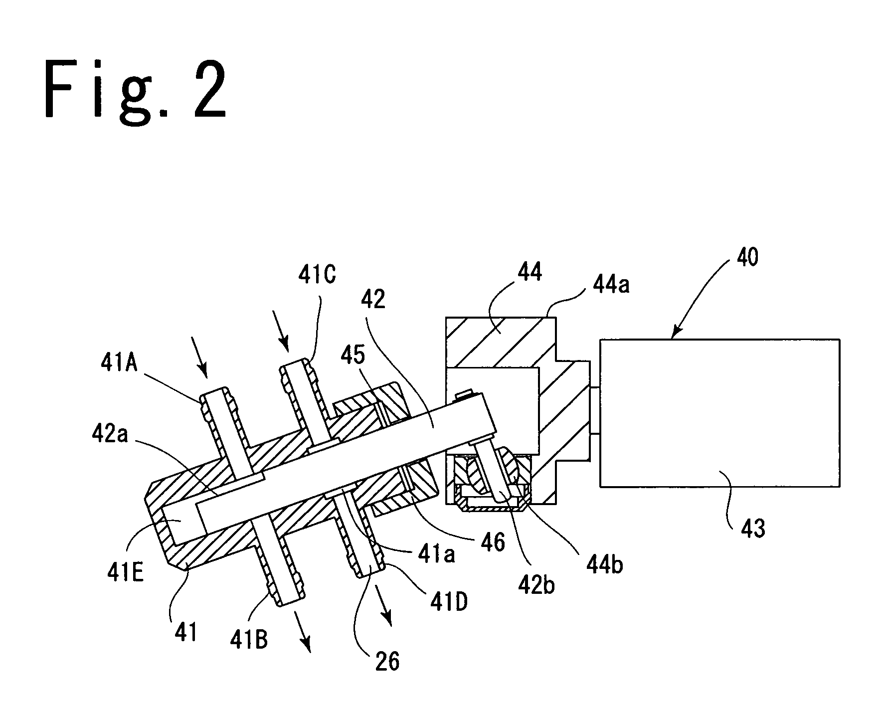
[0085]In the second embodiment, the extraction pump 121B is placed so as to be connected to the downstream side of the concentrate solution pump 121A in the washing passage 126, but may be connected to the upstream side. Further, the extraction pump 121B and the concentrate solution pump 121A may be connected to different washing passages 126, or only one of them may be connected to the washing passage 126.


PUM

PropertyMeasurementUnit
timeaaaaaaaaaa
adhesionaaaaaaaaaa
pressureaaaaaaaaaa

Abstract

A dialysis device 1 includes a water supply passage 15 for supplying clean water to solution supply chambers 35a and 35b, and a waste solution passage for discharging a used dialysis solution from solution collection chambers 34a and 34b, and the water supply passage includes a concentrate solution pump 21 that supplies a dialysis concentrate solution from concentrate solution supply source 19. The concentrate solution pump is a piston pump 40 that moves a piston 42 up and down in a cylinder 41 to feed a solution, the piston pump is provided in the way of washing passage 26 provided between the water supply passage and the waste solution passage, and an open / close valve 27 that intermittently opens and closes is provided in the washing passage to flow the clean water in the water supply passage through a gap between the cylinder and the piston.

Description

FIELD OF THE INVENTION[0001]The present invention relates to a dialysis device, and more particularly to a dialysis device having a piston pump.DESCRIPTION OF THE PRIOR ART[0002]Dialysis devices have used a piston pump that moves a piston up and down in a cylinder to feed a solution, as a extraction pump for feeding a dialysis solution (Patent Document 1: Japanese Patent No. 3395872).[0003]It is known that when a dialysis solution is fed by a piston pump, a deposition from the dialysis solution may cause adhesion between a cylinder and a piston. In this connection, Patent Document 1 discloses that in order to prepare a dialysis solution by mixing a dialysis concentrate solution and water, a single-patient-use dialysis device includes a supply line of water for diluting the dialysis concentrate solution, and thus a deposition that causes adhesion between a cylinder and a piston can be washed off even during dialysis by providing washing ports in a extraction pump of the single-patien...

Claims


Application Information

Patent Timeline
Patent Type & Authority Patents(United States)
IPC IPC(8): B01D61/26B01D61/28A61M1/14A61M1/16B01D61/24B01D61/30
CPCA61M1/1656B01D61/30B01D61/28B01D61/243
Inventor NISHIMURA, TAKAYUKIITOH, YOICHI
Owner SHIBUYA IND CO LTD
Why Eureka
Try Eureka