Fabrication of molds and mold components using a photolithographic technique and structures made therefrom

a technology of photolithography and mold parts, which is applied in the field of mold and mold component fabrication using a photolithographic technique and the structure made therefrom, can solve the problems of increasing product development time, incurring further long delays, and affecting the quality of molds, so as to achieve the effect of faster and cheaper

Inactive Publication Date: 2006-05-16
AFROMOWITZ MARTIN A
View PDF5 Cites 7 Cited by
  • Summary
  • Abstract
  • Description
  • Claims
  • Application Information

AI Technical Summary

Benefits of technology

[0007]The present invention eliminates one of more of the disadvantages of the diamond turning technology commonly used to fabricate mold inserts. Our process for making mold inserts is faster and cheaper than diamond turning. In addition, the surface shapes that can be created are not limited to those that are rotationally symmetric.

Problems solved by technology

A first disadvantage of this technology is that the diamond turning company may take a considerable amount of time to fabricate the inserts required for a mold.
On many occasions, after the initial delivery of the mold and testing of plastic integrated optical structures made therefrom, the mold fabricators' customer may require that the mold inserts be modified, in an attempt to secure the best optical performance of the plastic structure, which incurs further long delays.
This long turn-around time greatly increases product development time and may be unacceptable in a competitive marketing situation.
A second disadvantage of this technology is the high cost of fabricating the diamond turned inserts, which increases the costs of the mold, and ultimately, the cost of the plastic integrated optical structure.
A third disadvantage of this technology is that the conventional diamond turning process itself is limited in the surface shapes that it can create: All such surfaces must have rotational symmetry.
In fact, a common class of lens shapes, the cylindrical lens, does not conform to this requirement.
This lens shape also cannot be fabricated using conventional diamond turning.

Method used


Image

  • Fabrication of molds and mold components using a photolithographic technique and structures made therefrom
  • Fabrication of molds and mold components using a photolithographic technique and structures made therefrom
  • Fabrication of molds and mold components using a photolithographic technique and structures made therefrom

Examples


Embodiment Construction

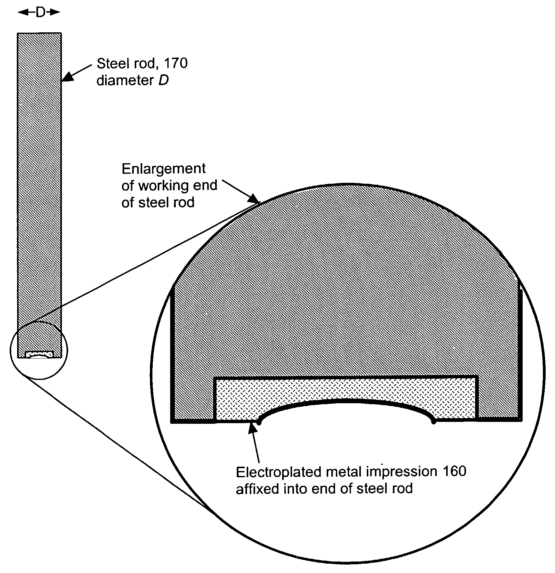
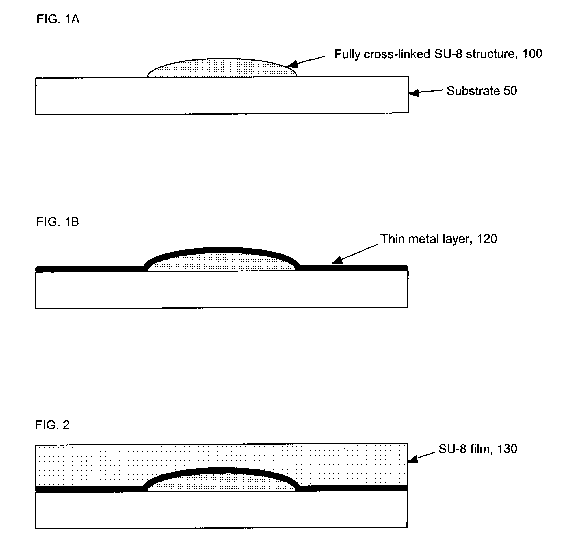
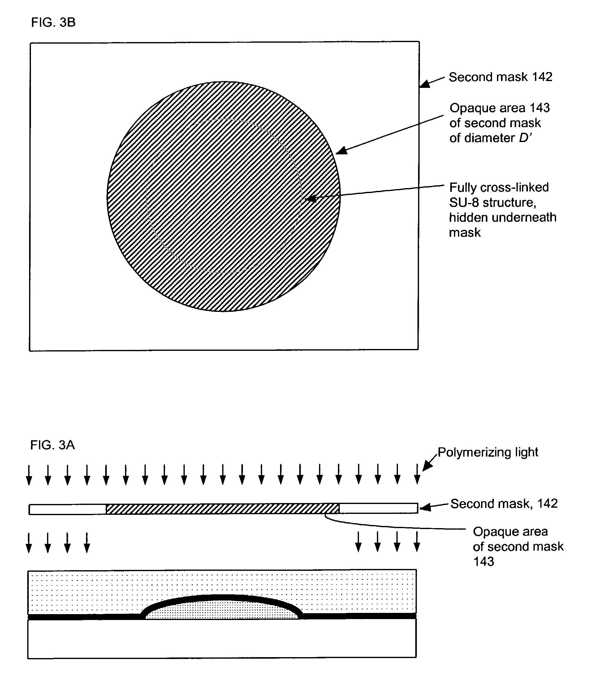
[0017]A new process is described for fabricating mold inserts comprising an unrestricted smoothly varying surface and the polymeric structures comprising an unrestricted smoothly varying surface, such as an integrated optical structure, that may be made in molds comprising such inserts.

[0018]Suppose that a mold is required for fabrication of an injection molded integrated optical structure comprising an optical element whose surface elevation is described mathematically by a smoothly varying function z(r, θ). The quantity z represents the deviation of the surface elevation of said optical element normal to a local reference plane as one moves radially away a distance r from a selected reference origin in a direction defined to be θ degrees away from a selected reference direction, both r and θ defined in said reference plane. Said optical element may be further specified as requiring a clear aperture of radius Rc, which means that within said clear aperture radius, said lens element...


PUM

PropertyMeasurementUnit
thicknessaaaaaaaaaa
wavelengthsaaaaaaaaaa

Abstract

The method includes the step of forming a solid epoxy member on a substrate, the epoxy member having an upper surface of desired configuration. A first metal layer is deposited on the epoxy member with the upper surface thereof conforming to the desired configuration. A layer of epoxy is deposited on the first metal layer and epoxy material from the epoxy layer is removed to create a well, exposing the metal layer on the epoxy member. A metal impression layer is then deposited in the well. The metal impression layer is then removed from the well and affixed to a mounting member as a mold component for injection molding of small structures.

Description

PRIOR APPLICATION[0001]This non-provisional application claims the priority of corresponding provisional patent application Ser. No. 60 / 347,799, filed on Jan. 11, 2002.TECHNICAL FIELD[0002]The present invention relates to techniques for fabricating molds and components used in molds, for use primarily in injection molding applications, and to the structures that may be made in such molds or molds comprising such components. In particular, the molds or mold components have working surfaces which are smoothly curved, such as may be used for molding integrated optical structures comprising small lenses and the like.BACKGROUND OF THE INVENTION[0003]Injection molding is a common technique for manufacturing small plastic structures in large quantity at low cost. When such structures comprise smoothly curved surfaces such as lens-like elements with maximum convexity or concavity less than or equal to a few millimeters, mold manufacturers generally use mold inserts, which are steel rods wit...

Claims


Application Information

Patent Timeline
Patent Type & Authority Patents(United States)
IPC IPC(8): B29C33/38B29D11/00
CPCB29D11/00432B29C33/3842
Inventor AFROMOWITZ, MARTIN A.
Owner AFROMOWITZ MARTIN A
Why Eureka
Try Eureka