Internally grounded filtering feedthrough

Active Publication Date: 2006-05-16
PACESETTER INC
View PDF6 Cites 124 Cited by
  • Summary
  • Abstract
  • Description
  • Claims
  • Application Information

AI Technical Summary

Benefits of technology

[0018]In addition, the back fill port is designed as a feature of the housing. This manner of construction will save additional assembly steps for that component. This feature is dimensionally configured to simulate the currently used back fill port and to minimize the functional impact to the current manufacturing process.
[0019]The integration of the back fill port to the housing is required for the purpose of the invention but the invention is not limited to an eight pole feedthrough construction. Rather, this concept can easily be integrat

Problems solved by technology

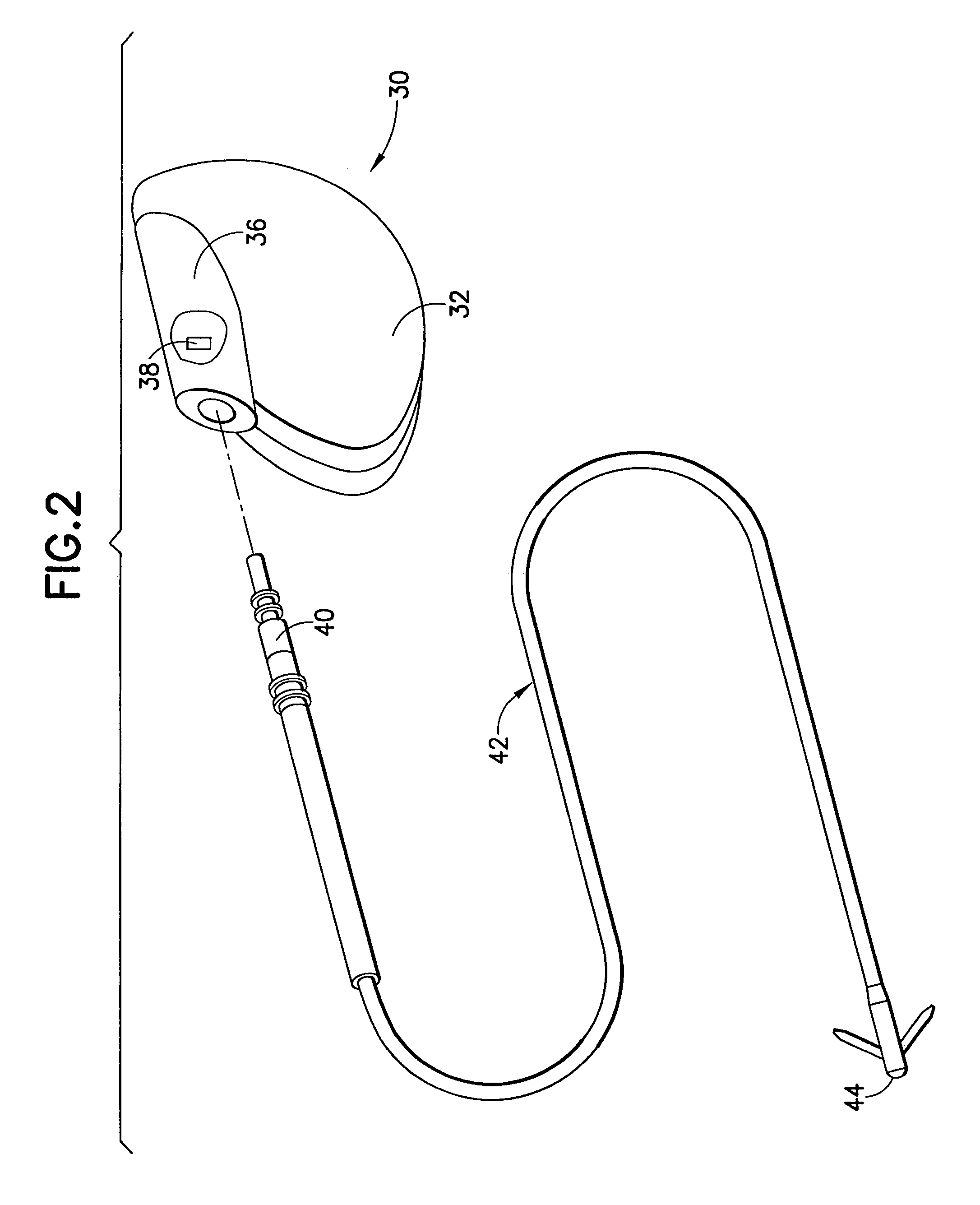
Because of their conductive properties, these leads effectively act as an antenna and thus tend to conduct unwanted electromagnetic interference (EMI) signals.
These EMI signals may be transmitted to the medical device and interfere with normal operations.
In implantable cardioverter/defibrillators, charging and delivery of a defibrillating shock can cause EMI which adversely affects the sensing circuits or the operation of the device.
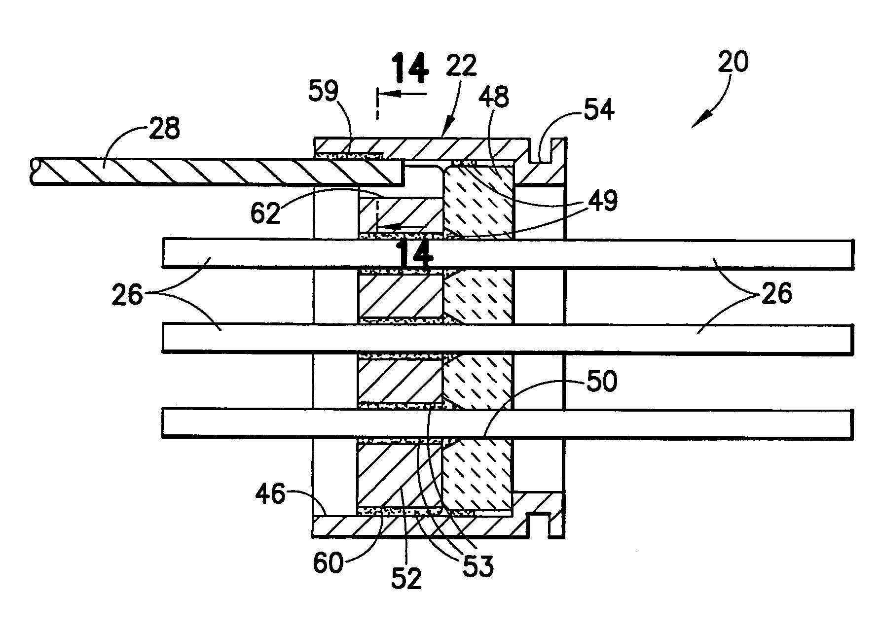
The size of the feedthrough device limits how small an implantable device can be, because the width of a pacemaker or defibrillator case must be, at minimum, slightly larger than the width of the feedthrough.
Of the noted patents, only Bealka et al. discloses a ground wire which is mounted within the outer boundary of the ferrule, but the feedthrough device of that disclosure does not provide for signal filtration.
Some of the current practices employed for grounding electronic devices to a case in these feedthrough assemblies involve steps that use unnecessary space, are inefficient, and may cause yield problems.
Welding, however, is more labor intensive and expensive than brazing.
Additionally, either brazing or welding the ground wire directly to the ferrule takes up a significant amount of space on the ferrule, because such a procedure requires an additional braze or weld joint.
It also makes orienting the lead more difficult, because there is nothing supporting the sides of the ground wire.
This additional braze joint must also be spatially separated from

Method used


Image

  • Internally grounded filtering feedthrough
  • Internally grounded filtering feedthrough
  • Internally grounded filtering feedthrough

Examples


Embodiment Construction

[0041]Referring to FIG. 1, there is shown a perspective view of a feedthrough device 20 incorporating features of the present invention. Although the present invention will be described with reference to the embodiments shown in the drawings, it should be understood that the present invention can be embodied in many alternate forms or embodiments. In addition, any suitable size, shape or type of elements or materials compatible with the invention may be used. The feedthrough device 20 includes a conductive ferrule 22 having an outer peripheral surface 24 defining its outermost boundary. A plurality of lead wires 26 extend through the ferrule 22 but are electrically isolated from the ferrule. A ground wire 28 is coupled to the ferrule and is attached to the feedthrough device within its outermost boundary as defined by the outer peripheral surface 24.

[0042]Viewing FIGS. 2–6, the feedthrough device 20 is seen to be a component of a medical implant device 30 for stimulating tissue of a...


PUM


Abstract

A feedthrough device includes a conductive ferrule having an outer peripheral surface defining the outermost boundary of the feedthrough device, an insulator, a lead wire electrically isolated from the ferrule extending through the insulator, a filter capacitor adjacent the insulator through which the lead wire extends in conductive relation therewith, and a ground wire coupled to the ferrule and to the insulator within the outermost boundary of the feedthrough device. The ferrule has an inner peripheral surface defining an opening therethrough and each of the insulator and the filter capacitor has an outer peripheral surface proximate the inner peripheral surface, a counterbore in the outer peripheral surface of each of the insulator and filter capacitor, an end of the ground wire being received in the counterbore and brazed to the ferrule and insulator. Alternatively, an end of the ground wire is welded to the inner peripheral surface of the ferrule.

Description

FIELD OF THE INVENTION[0001]The present invention is directed to feedthrough devices having grounded leads. In particular, the invention relates to feedthrough devices with internally grounded filtering leads that are suitable for use in implantable medical devices or pulse generators, such as pacemakers, defibrillators, and the like.BACKGROUND OF THE INVENTION[0002]A conventional implantable pacemaker or cardioverter / defibrillator system comprises at least one electrode attached to the heart and connected by a flexible lead to a shock or pulse generator. This generator is a combination of a power source and the microelectronics required for the system to perform its intended function. Many pacemakers and cardioverter / defibrillators in current use incorporate circuits and antennae to communicate non-invasively with external instruments called programmers. These implantable devices have the capability of correcting dangerous arrhythmias and fibrillation by applying selected stimulati...

Claims


Application Information

Patent Timeline
IPC IPC(8): H01G4/35
CPCH01G9/10H01G4/35A61N1/3754
Inventor IMANI, REZAHAWKINS, RODNEY J.
Owner PACESETTER INC
Why Eureka
Try Eureka