Scheduling control system and switch

a control system and control switch technology, applied in the field of scheduling control system, can solve the problems of difficult hardware implementation, complicated logical operation, complicated arithmetic process, etc., and achieve the effect of speeding up processing

Inactive Publication Date: 2006-05-16
FUJITSU LTD
View PDF14 Cites 48 Cited by
  • Summary
  • Abstract
  • Description
  • Claims
  • Application Information

AI Technical Summary

Benefits of technology

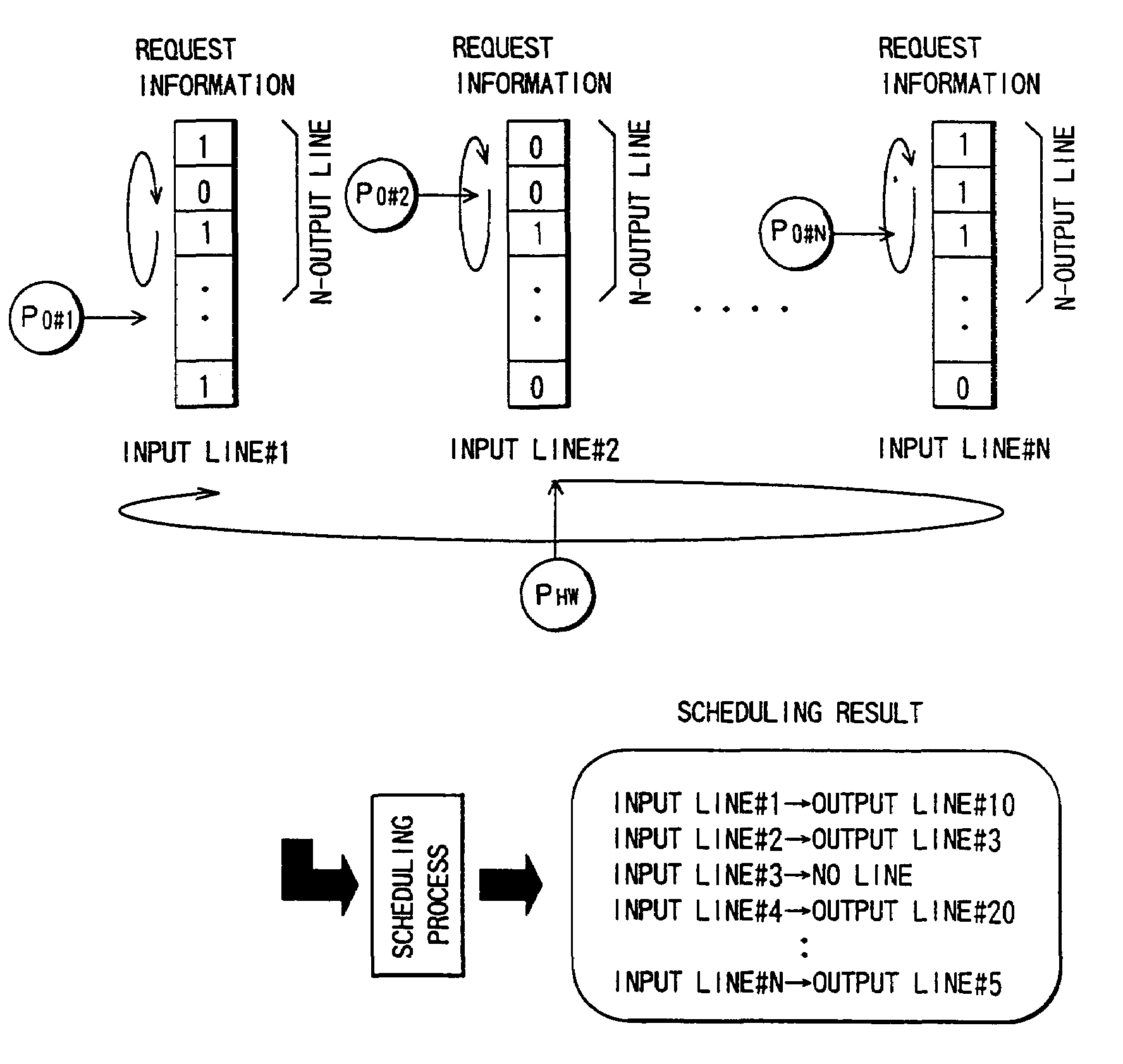
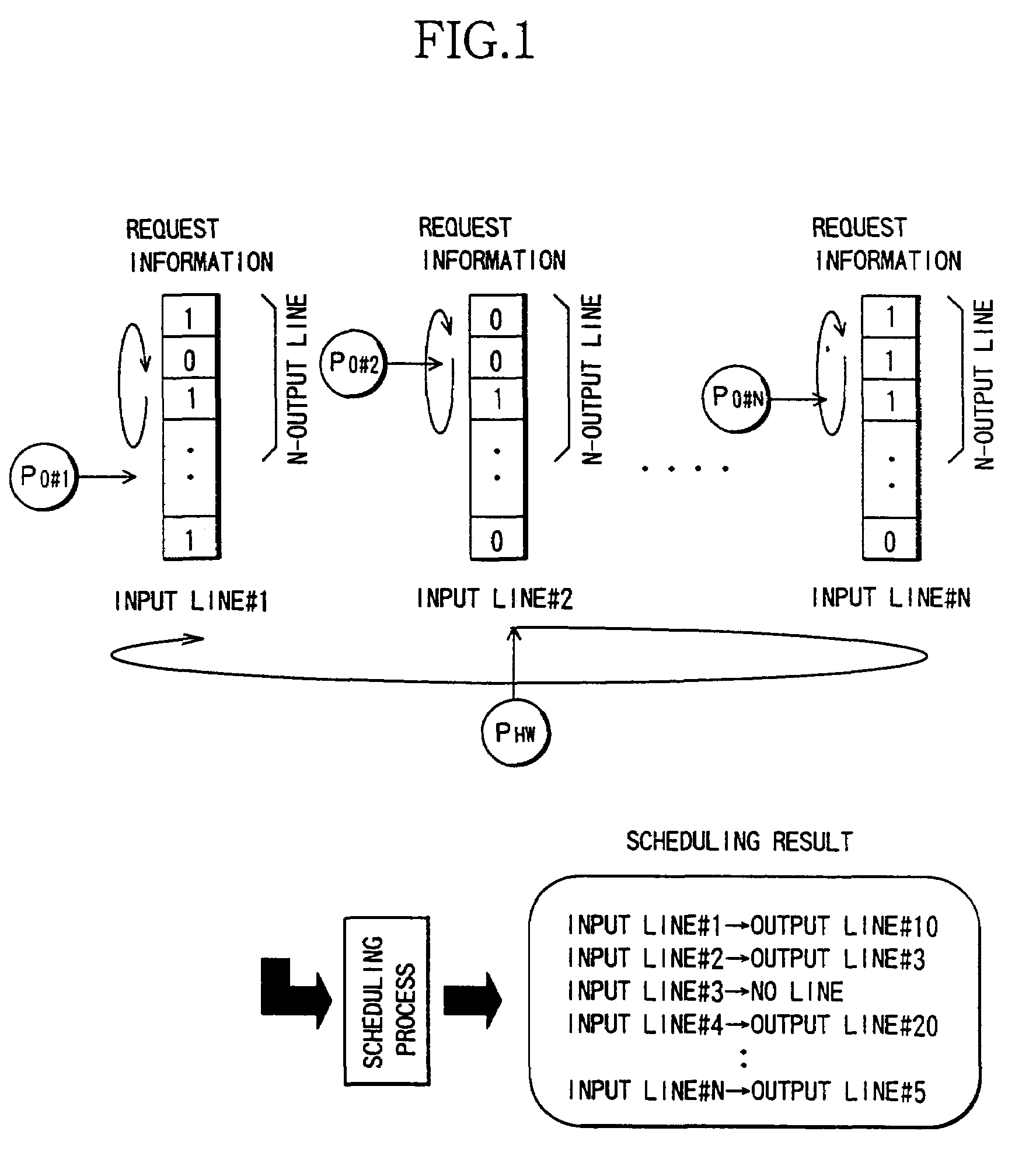
[0120]Herein, bitmap information (in which “1” represents an existence of the request, while “0” represents non-existence of the request) of N bits (4 bits in this example), is divided into two masks from a point indicated by the intra-highway pointer. Then, the mask after the intra-highway pointer is referred to as a mask-A, and the mask before the intra-highway pointer is referred to as a mask-B. This can be easily actualized by preparing exclusive two mask patterns (Masks-A, B in FIG. 15) with the intra-highway pointer being interposed therebetween, and taking a logic AND between the mask patterns and the N-bits request information.
[0281]Thus, according to the thirty fifth aspect of the invention, the synchronization is not needed, so that the circuits for the synchronization can be reduced. It is also possible to decrease a time needed for the synchronizing process when starting up the system and an extension thereof. Note that the construction of providing the buffer at each lattice point is the same as that of the switch on the side of the cross-point buffer. On the input buffer side, however, since the band for transferring to each output line from each lattice point is ensured, only the buffer for absorbing the delay between the packages may suffice, with the result that an extremely small quantity of buffers may suffice.

Problems solved by technology

Further, according to another system for obtaining such a combination as to maximize an I / O combination, complicated arithmetic processes are repeatedly executed for obtaining an optimum combination.
Further, according to the system for obtaining the maximum combination, the complicated logical operation is needed and is hard to be actualized by hardware.
Then, there arises a problem of causing a remarkable decline of forwarding delay from a high-load input line if there are forwarding requests from a plurality of lines with different input loads (unequal loads) with respect to one single output line.
Further, in the large-scale switch accommodating a multiplicity of lines, if the LB counter for band control is structured of logics, a quantity of hardware becomes tremendous.
Moreover, if constructed by use of a memory, a problem is that it is difficult to access simultaneously within the 1-packet time.
Furthermore, when the large-scale switch is constructed of a plurality of LSIs or packages, there are required inputs / outputs (I / O) between the LSIs or the packages, of which the number is four times the number of cell highways, and the number of I / Os (inputs / outputs) results in a bottleneck.
A problem is that there arise necessities for structuring plural types of LSIs or packages because of I / O lengths being different and for making a phase adjustment.
In addition, when the large-scale switch is constructed of the plurality of LSIs or packages, according to the batcher sorter type etc, it is required that the unit switch be inserted in a path on a minimum scale on the occasion of an extension of the switch scale, and hence the paths are required to be re-configured, resulting in such a problem that the system must be stopped when extending the switch scale.
Therefore, a problem is that the above technology can not be applied to a scheduling system in which the input buffer is constructed of a logical queue per output route, and the input lines can not be univocally determined according to such a sequence of the output line numbers as to determine the output route with respect to each input buffer under contention control.
Further, if the switch, the input buffer and the scheduler are structured extending over a plurality of packages, there might occur desynchronization of a cell level between the packages.
In the system for transferring the frame indicating the cell heading and the data in parallel as shown in FIG. 7, however, there exists such a problem that asynchronism of the cell level can not be detected.

Method used


Image

  • Scheduling control system and switch
  • Scheduling control system and switch
  • Scheduling control system and switch

Examples


embodiment 1

[0363]FIG. 38 shows one embodiment of a lowest number selection circuit illustrated in FIG. 15, wherein a white block indicates a selector circuit, and a screened block is constructed of two pieces of logic circuits for giving the following outputs X, Y with respect to inputs A, B.[0364]X=A or B[0365]Y=(A xor B) and B

[0366]This implies that X takes a logical sum of the two inputs, and Y is a logic for selecting a lower-numbered input, having “1”, of the two inputs. The following is one example of a table of truth value of the lower number selection logic.

[0367]

Input (A)Input (B)Output (Y)000011100110

[0368]One example of an operation of the lower number selection logic will be explained with reference to the circuit in FIG. 38.

[0369]In this embodiment, the mask-A (after an inter-highway pointer) described above is obtained in an upper half in the Figure, while the mask-B (before an intra-highway pointer) is obtained in a lower half in the Figure.

[0370]In the mask-A, a line number is ...

embodiment 2

[0444]FIG. 43 shows a whole architecture of the present system.

[0445]As illustrated in FIG. 43, in accordance with an embodiment 2, the cells arrived via the input lines are held by the input buffers, then inputted to an (N×N) configured switch by an indication given from the scheduler, and outputted from N-lines of output lines.

[0446]Herein, inversion control of the inter-highway pointer will be explained referring to FIG. 44. A (4×4) configured switch is assumed in FIG. 44.

[0447]Referring again to FIG. 44, the scheduling of the first time starts with the input line #0 and is performed in sequence such as the input lines #0, #1, #2 and #3.

[0448]If the scheduling proceeds in the sequence in only one direction, the inter-highway pointer shifts second time in the forward direction, and the scheduling proceeds in sequence such as #2, #3, #0, #1 starting from the input line #2. Herein, when considering the scheduling sequence with an emphasis upon the input lines #0 and #1, a larger qua...

embodiment 3

[0451]An embodiment of a pipeline processing system using the inversion control explained above, is hereinafter be described.

[0452]The configuration of the 4×4 switch has been exemplified in the embodiment 2, the four input lines may be scheduled within a 1-packet time. If accommodating a larger number of lines, however, it is difficult to finish the processing of all the lines within the 1-packet time.

[0453]Such being the case, the pipeline processing architecture is structured by shifting in time the scheduling start input line, thereby avoiding a problem in terms of a processing speed. This is how the present embodiment is.

[0454]FIG. 45 shows a pipeline sequence. A start number of each pipeline deviates in time, whereby a contention is hard to occur. The numerals in the Figure indicates the serial numbers of the scheduling target input lines. In this example, the scheduling of the two lines is executed within the 1-packet time. Then, the scheduling is structured so that the sched...


PUM


Abstract

A scheduling system is capable of causing no deterioration of characteristics even under equal and unequal loads, eliminating the necessity for high-speed repetitive scheduling and complicated arithmetic processes, simplifying its architecture and having its processing speed which does not depend upon a device capability. For attaining this system, an inter-highway pointer is updated to an adjacent line (rightward) when the scheduling for all the lines are finished. If the inter-highway pointer is updated N-times in the same direction (clockwise), the same pointer is updated to an adjacent line in a reverse direction (counterclockwise) in next N-processes of scheduling.

Description

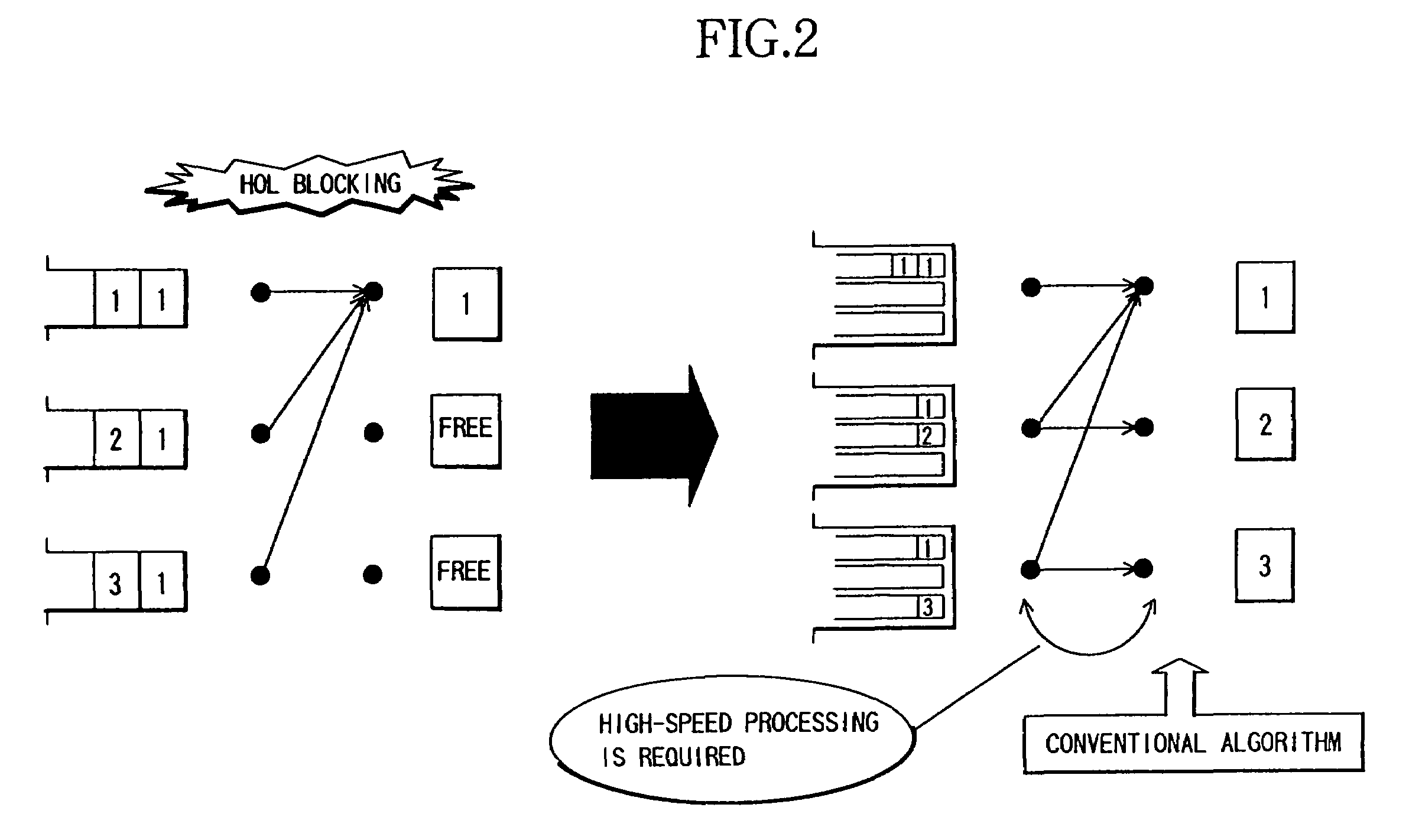
BACKGROUND OF THE INVENTION[0001]The present invention generally relates to a scheduling control system, and more particularly to a technology effective in an application to the scheduling control system in an input buffer type switch, which is defined as one method of constructing a large-scale ATM switch.[0002]With an explosive spread of Internet and an advent of media dealing with large-capacity and high-quality information over the recent years, it has been highly expected to prepare a large-scale communications infrastructure capable of flexibly dealing with the large-capacity data. Then, the concerns are concentrated upon a switch having a capacity as large as several hundreds of giga order to several tera order as a key for actualization thereof.[0003]A basic input buffer type switch (on the left side in FIG. 2) having a unit buffer for every input route, has a problem of HOL (Head of Line) blocking, and it is known that a throughput thereof increases up to approximately 58.6...

Claims


Application Information

Patent Timeline
Patent Type & Authority Patents(United States)
IPC IPC(8): H04L12/56H04J7/00H04L12/43H04L12/54H04L12/28H04L47/22H04L47/52H04L47/6275
CPCH04L12/5601H04L12/5693H04L41/0896H04L49/1553H04L47/6225H04L2012/5681H04L49/3045H04L2012/5679H04L47/50
Inventor MATSUOKA, NAOKIKAWARAI, KENICHITOMONAGA, HIROSHIKATO, TSUGUO
Owner FUJITSU LTD
Why Eureka
Try Eureka