Finding cell phones in rubble and related situations

a technology of radio transmission and cell phone, applied in the field of communication, can solve the problems of insufficient precision of e-911 system techniques, inability to give the location of cell phone within the building (e.g., within the room), and inability to locate cell phone with high precision, so as to achieve the effect of reducing transmission tim

Active Publication Date: 2006-05-16
NORTHROP GRUMMAN SYST CORP
View PDF9 Cites 43 Cited by
  • Summary
  • Abstract
  • Description
  • Claims
  • Application Information

AI Technical Summary

Problems solved by technology

These techniques are designed to locate a cell phone to a building, but cannot give the location of the cell phone within the building (e.g., within a room).
Therefore, current E-911 system techniques are not precise enough to locate a cell phone in a search and rescue operation.
Another problem with locating cell phones with high precision is due to multipath.
Another source of impairment is additive noise or interference from other cellular phones and base stations.
Therefore, it is difficult to detect a weak signal, for example, in a pile of rubble, amongst the other interfering signals due to multipath and other cell phone signals within the same frequency range.
As the events of 11 Sep. 2001 have demonstrated, there exists today no practical method to locate quickly and accurately a cell phone or other radio transmitter in a pile of building rubble.
Various attempts to solve some of these problems using Global Position System (GPS) technology have been made, but fail for various reasons.
For example, most of today's cell phones have no capability to receive GPS signals.
Additionally, GPS signals are too weak to be received inside most buildings, and location estimates derived from GPS signals received inside buildings have greatly degraded accuracies due to multipath reflections.
Even under the best conditions, GPS fundamentally does not provide the location accuracy required for rescue operations.

Method used


Image

  • Finding cell phones in rubble and related situations
  • Finding cell phones in rubble and related situations
  • Finding cell phones in rubble and related situations

Examples


Embodiment Construction

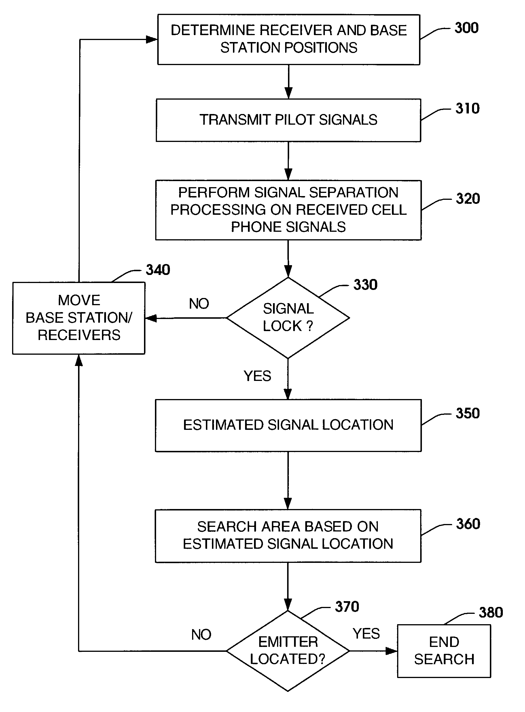
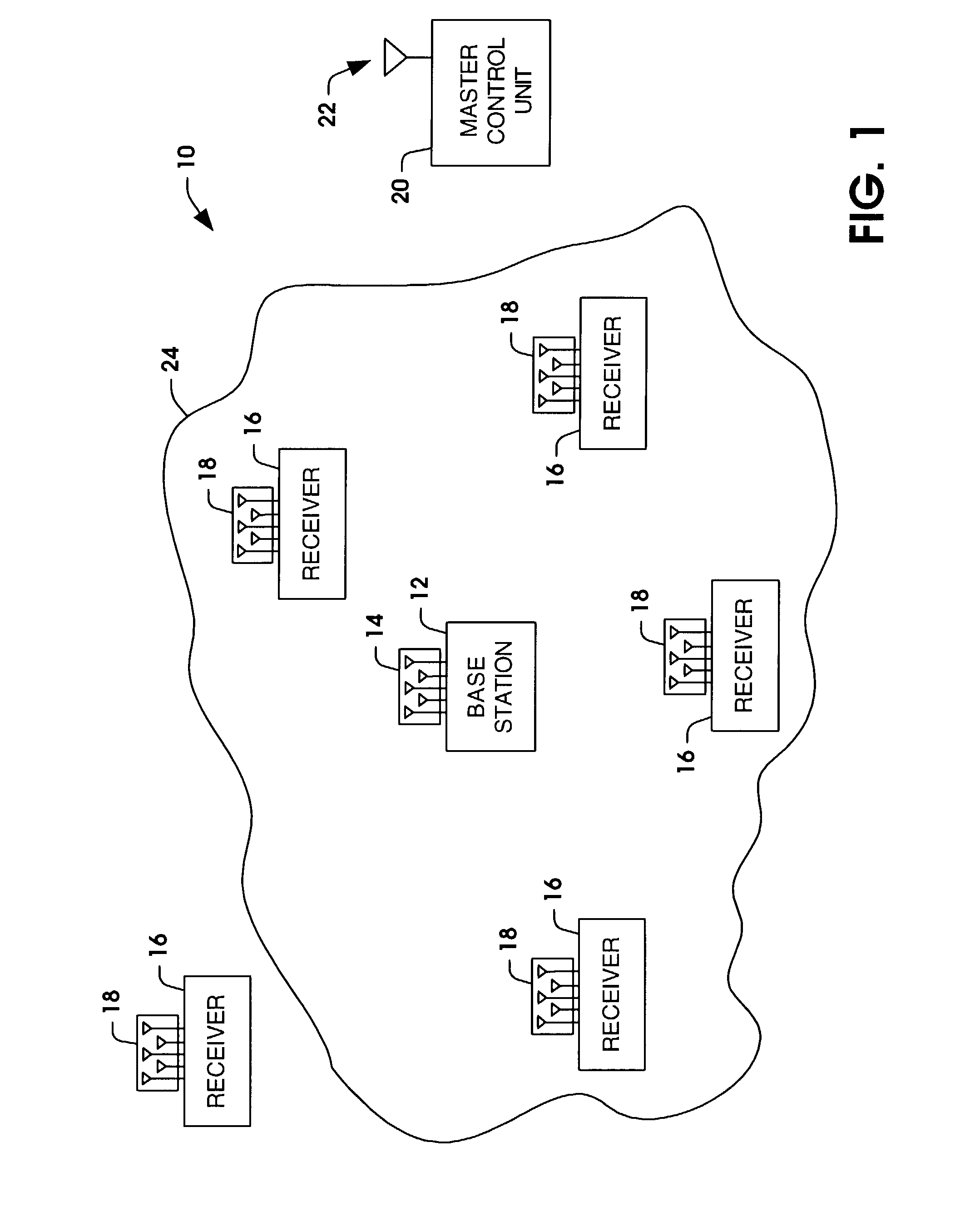
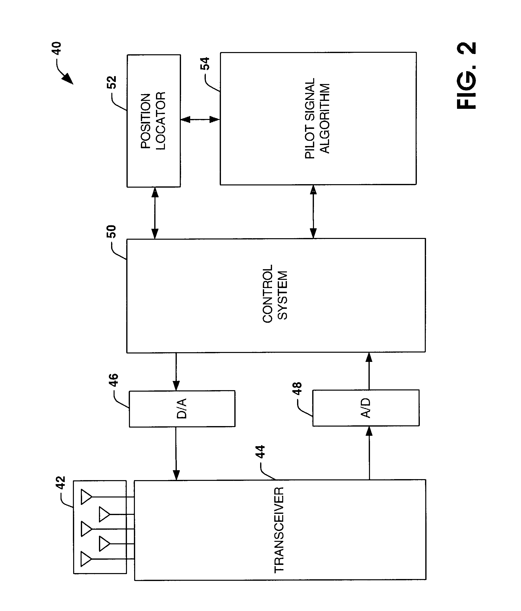
[0017]The present invention provides for systems and methods for locating a radio transmission signal in a rescue operation. Receivers are located around the rescue area to monitor for transmission signals from the one or more radio transmission emitter devices (e.g., cell phones). A calibration routine is executed to determine geographical position information of the receivers. A base station pilot signal is employed for connecting with the radio transmission devices located in a rescue area. A signal separation routine extracts desired transmission signals from other signals coexisting on similar frequency bands and interfering with the desired transmission signals. A direction finder algorithm can be employed to determine at each receiver location the direction from which one or more of the desired transmission signals are being transmitted. The direction data, raw signal data and receiver position data are provided to a master controller to determine an estimated location of the...


PUM


Abstract

Systems and methods are provided for locating a transmission signal from a radio transmission emitter device, such as a cell phone, in a rescue area. A pilot signal is employed to lock onto a transmission signal of one or more radio transmission devices located in a rescue area. A signal separation routine extracts desired transmission signals from emitter devices located in the rescue area from other signals coexisting on similar frequency bands and interfering with the desired transmission signals. An estimated location of transmission signals from emitter devices located in the rescue area is determined based on one or more transmission signal location techniques. The area is searched based on the estimated location of the transmission signal. If the emitter transmitting the transmission signal is not found, devices in the system are moved and the location estimation is repeated.

Description

TECHNICAL FIELD[0001]The present invention relates to communications and, more particularly, to systems and methods for locating a radio transmission emitter device.BACKGROUND OF THE INVENTION[0002]In certain applications it is desirable to determine the location of an emitter (e.g., cell phone) of a radio transmission signal. Precise location information in a cellular telephone network is desirable for various reasons. Location information can be employed to aid hand-off, increase signal sensitivity, reduce co-channel interference and increase cell capacity. Additionally, location information is utilized in 911 dispatching, tracking unauthorized cell phone usage, and tracking or locating commercial and government vehicles. The FCC has required that Phase I of a wireless emergency 911 system (E-911) provide a 911 agent (a Public Safety Answering Point) with caller number and cell site location, while phase II of the E-911 system requires that caller latitude and longitude with an er...

Claims


Application Information

Patent Timeline
Patent Type & Authority Patents(United States)
IPC IPC(8): H04M11/04H04W4/90H04W64/00
CPCH04W64/00H04W4/22H04W76/007H04W76/50H04W4/90
Inventor SIEGEL, NEIL G.STEARNS, STEPHEN D.JENNETTI, ANTHONY G.
Owner NORTHROP GRUMMAN SYST CORP
Why Eureka
Try Eureka