Virtual modular relay device

a virtual electronic device and modular technology, applied in computer control, program control, instruments, etc., can solve the problems of time and money costs of reprogramming, inability to customize the output and/or control functions of such pre-programmed virtual electronic devices, and inability to save time and money in system configuration

Inactive Publication Date: 2006-05-16
GENERAL ELECTRIC CO
View PDF42 Cites 8 Cited by
  • Summary
  • Abstract
  • Description
  • Claims
  • Application Information

AI Technical Summary

Benefits of technology

[0007]This invention offers advantages and alternatives over the prior art by providing an intelligent virtual modular relay device wizard for a power management control system that automates the development of a virtual modular relay device. The vi

Problems solved by technology

Thus, the pre-programmed virtual electronic devices save a great deal of time and money in configuring the system.
However, the functionality (i.e., the output and/or control functions) of such pre-programmed virtual electronic devices cannot be customized without re-programming the virtual device and incurring the time and money costs of such reprogramming.
Fortunately, most intelligent

Method used


Image

  • Virtual modular relay device
  • Virtual modular relay device
  • Virtual modular relay device

Examples


Embodiment Construction

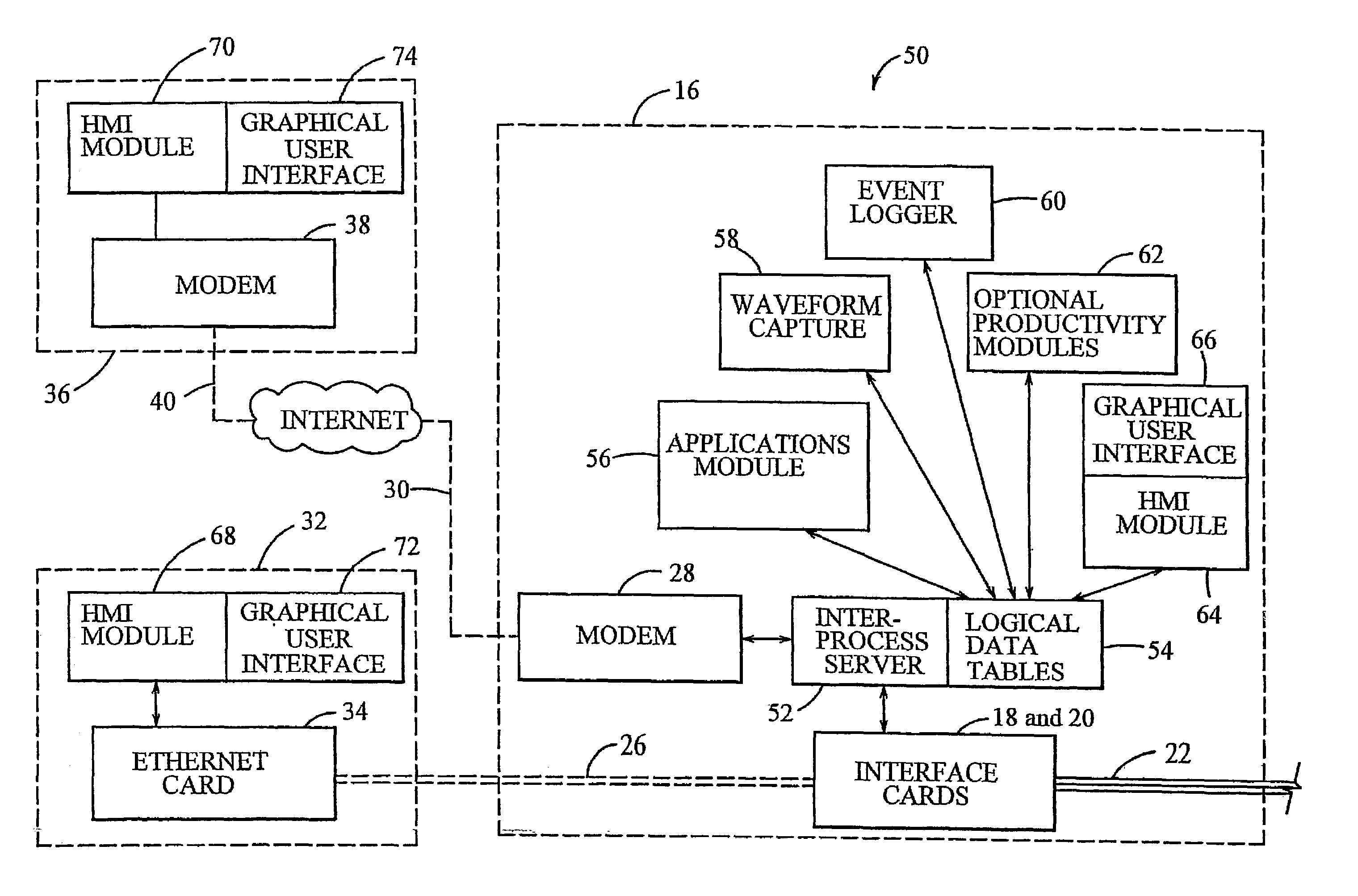
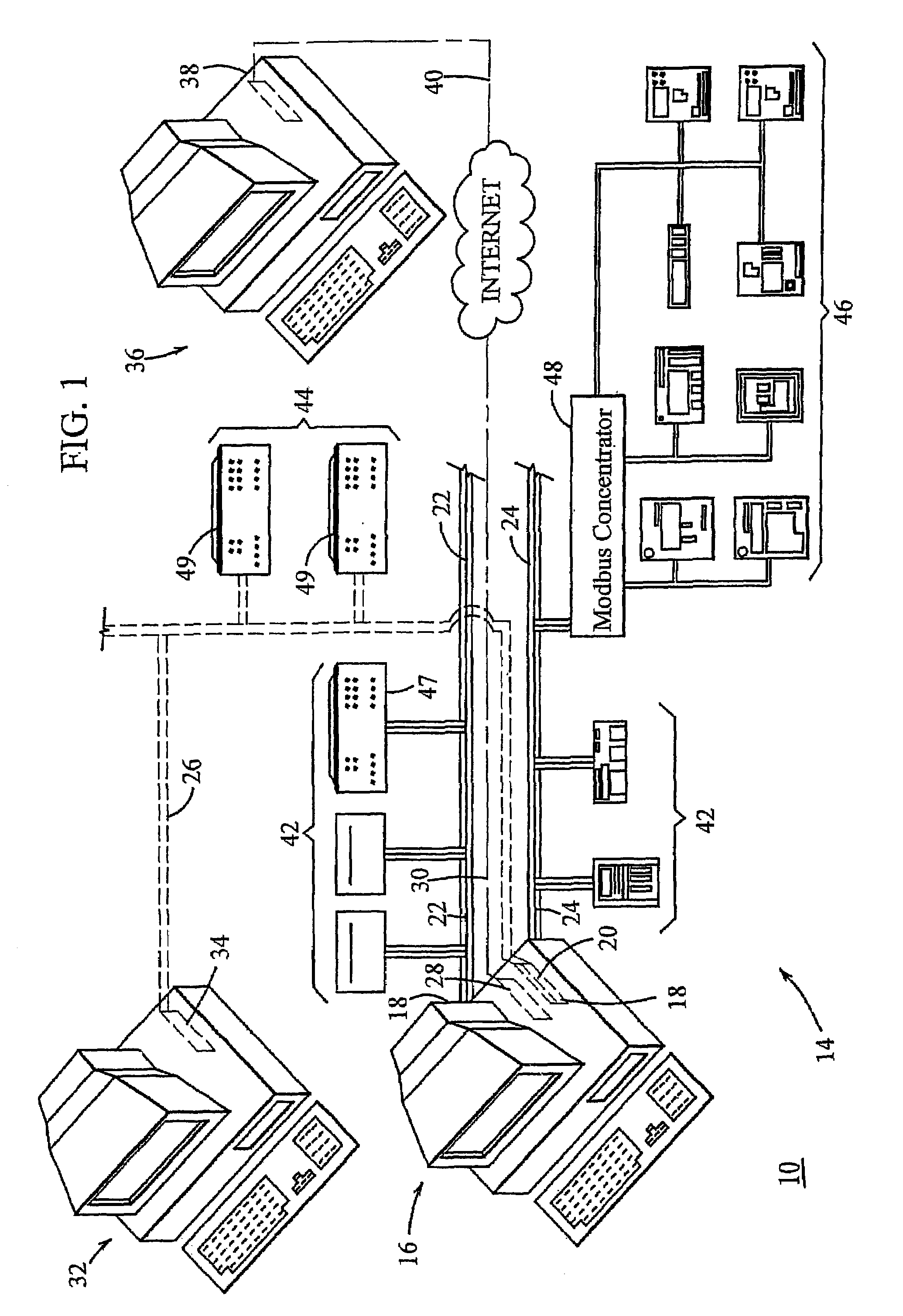
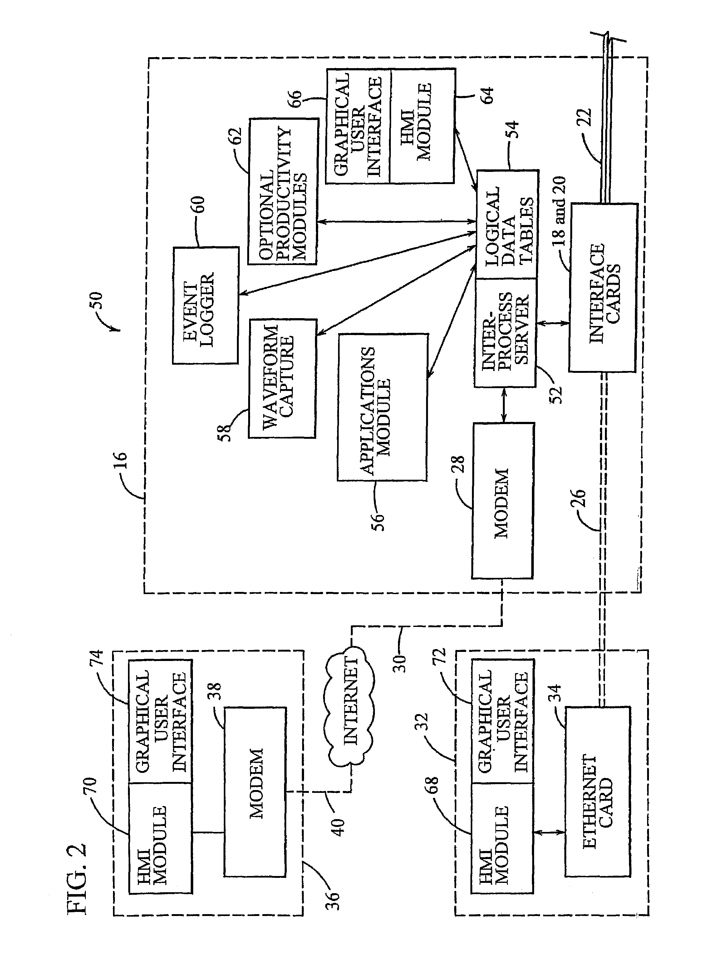
[0017]Referring now to FIG. 1, a computerized power management control system (“PMCS”), generally designated 10, provides a three-dimensional (“3-D”) virtual switchgear cabinet 12 (see FIG. 3) for displaying a visual indication of the status or condition of a plurality of intelligent electronic devices 14 of an electrical distribution system (not shown). The PMCS 10 comprises a server computer 16, e.g., an IBM-PC AT compatible machine which is based on a Pentium processor, having network interface cards 18 and 20 installed in its I / O slots. The server computer 16 contains software for monitoring and controlling selected aspects of power usage / consumption, as described in more detail hereinafter. Network interface cards 18 and 20 comprise standard RS485 and Ethernet interface cards, respectively. RS485 interface cards 18 provide I / O ports that form part of industry standard ModBus RTU networks 22 and 24. Ethernet card 20 provides an I / O port that forms part of a 10BaseF or redundant ...


PUM


Abstract

A computerized power management control system (10) includes a virtual modular relay device (82) for providing input and output data to and from a corresponding, actual modular relay device (47 or 49). Virtual modular relay device (82) is displayed in a window (90), with the upper left-hand corner of window (90) including a graphical depiction (92) of the modular relay device. Immediately below the graphical depiction (92) is a communications status indicator (94), which shows the status of communications (connected/disconnected) between the virtual device (82) and an inter-process communications server (52). Various fields (96) appear along the left-hand side of window to identify the modular relay unit (47 or 49). Below identification fields (96) are a plurality of buttons (98), each of which allow the user to activate a program module. Buttons (156 and 154) can be customized by the user to activate any program module. Tabbed pages (102) allow the user to quickly view numerous functions without cluttering the computer screen. The functions depicted on each of the tabbed pages (102) are user-defined. A program utility automatically configures the virtual modular relay device (82) graphic and links the virtual intelligent electronic device (82) to its actual counterpart (47 or 49) so that input and output signals may be sent between the two.

Description

CROSS REFERENCE TO RELATED APPLICATIONS[0001]This Application is a continuation of U.S. application Ser. No. 09 / 397,395 filed Sep. 16, 1999 now abandoned entitled A VIRTUAL RELAY DEVICE, which is incorporated by reference in its entirety.BACKGROUND OF THE INVENTION[0002]The present invention relates generally to a power management control system and, in particular, to software that implements and automates the development of a virtual modular relay device.[0003]Power management control systems allow an operator to monitor and control a variety of intelligent electronic devices within an electrical distribution system. Such devices can include relays, meters, switches, etc., which are generally mounted within a common switchgear cabinet to create a control panel. Modem power management control systems also include modular relay devices, such as General Electric Co.'s Universal Relay family of modular relay devices, mounted within the switchgear cabinet. A modular relay device allows ...

Claims


Application Information

Patent Timeline
IPC IPC(8): G06F15/16G06F15/177G05B19/00G05B19/042G06F3/048G06F3/0487H02B15/00
CPCG05B19/00G05B19/0426G05B2219/23258G05B2219/23261G05B2219/25019Y04S20/227G05B2219/25092G05B2219/25349G05B2219/36033Y02B70/3241G05B2219/25067Y02B70/30Y04S20/20
Inventor THOMAS, ROBERT P.PETRIZZI, JAMESMEAGHER, PATRICKMATHUR, SUNILKARANAM, RAJAIAHBUTLAND, GEOFF
Owner GENERAL ELECTRIC CO
Why Eureka
Try Eureka