Combustion ignition

a combustion ignition and combustion device technology, applied in the direction of machines/engines, hot gas positive displacement engine plants, intermittent jet plants, etc., can solve the problems of nitrous oxide emission, high operating temperature and pressure, noise and vibration,

Inactive Publication Date: 2006-05-23
UNITED TECH CORP
View PDF35 Cites 55 Cited by
  • Summary
  • Abstract
  • Description
  • Claims
  • Application Information

AI Technical Summary

Problems solved by technology

Achieving reliable detonation imposes complexity costs.
There may be operational drawbacks including noise and vibration, high operating temperatures and pressures, and nitrous oxide emission.

Method used


Image

  • Combustion ignition
  • Combustion ignition
  • Combustion ignition

Examples


Embodiment Construction

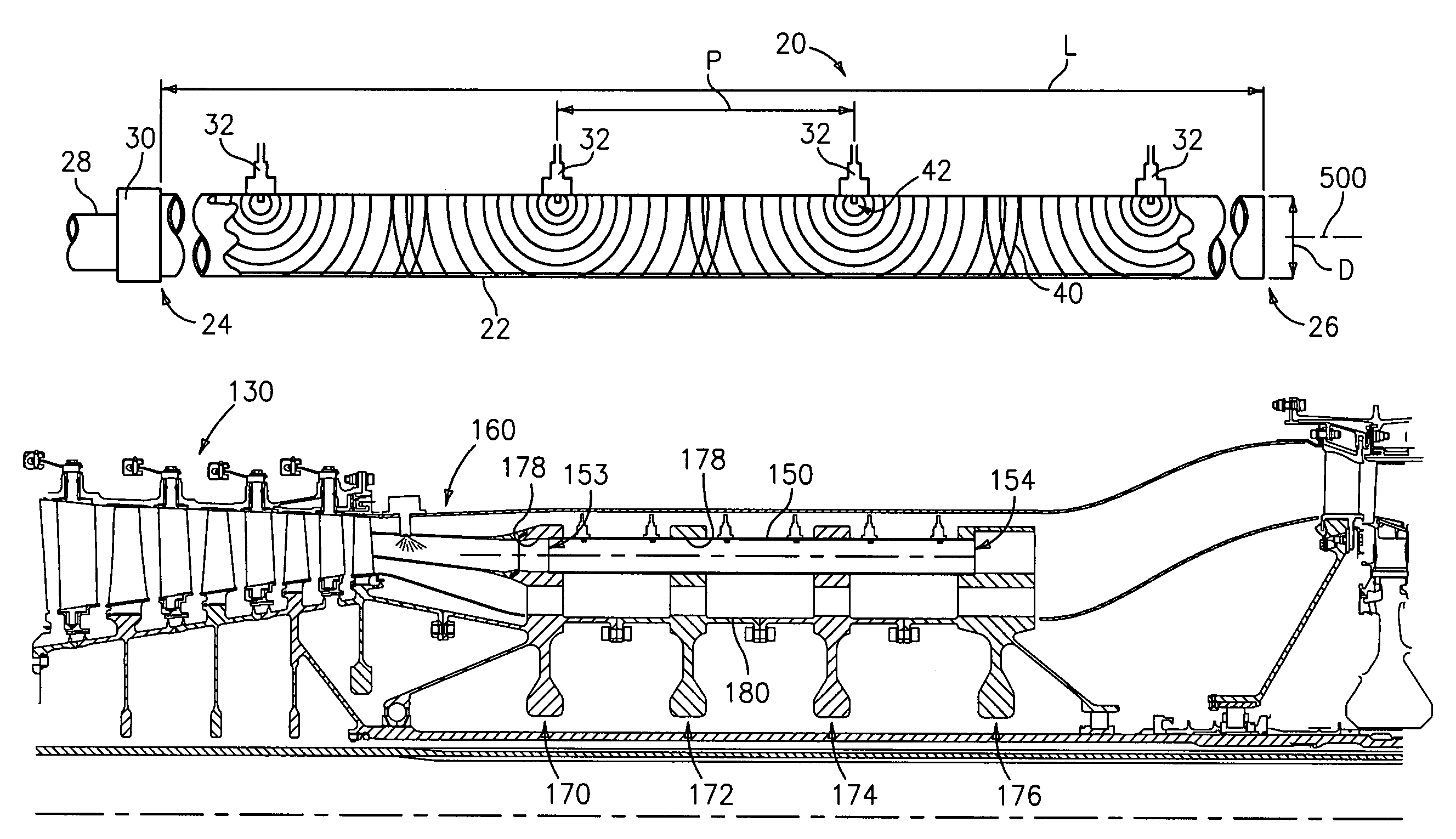
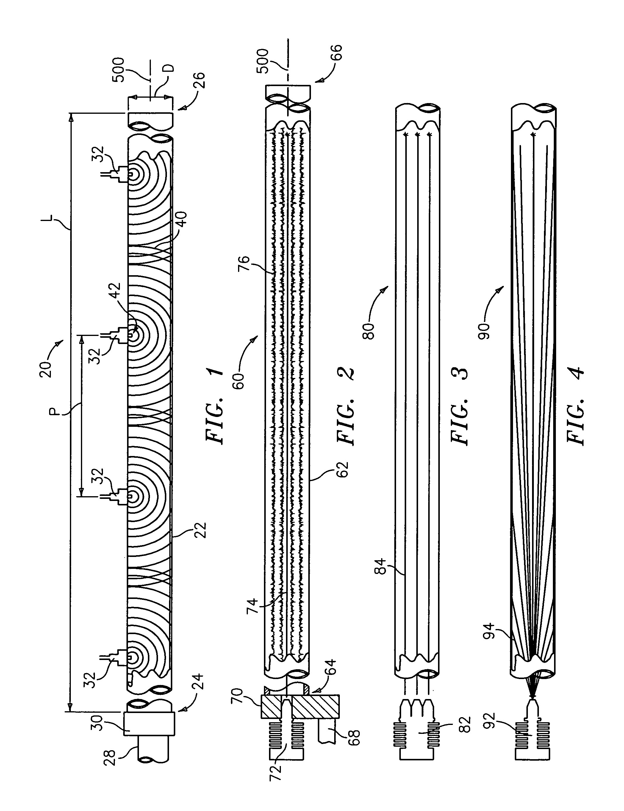
[0022]FIG. 1 shows a device 20 having a containment tube 22 extending along a central longitudinal axis 500 from an inlet end 24 to an outlet end 26. The inlet end is coupled to a fuel / air conduit 28 by a valve 30. A series of igniters 32 are positioned at various locations along the tube. The tube has an overall length L and the igniters are positioned at an exemplary pitch P. The tube interior has a characteristic transverse dimension identified as a diameter D. When triggered, each igniter produces a deflagration pulse 40 which propagates a flame front radially outward from an associated ignition point 42 at a subsonic speed(e.g., under about 2,000 feet per second (fps) any typically in the vicinity of 1,000 fps). With multiple igniters, near total combustion will be achieved in the time required for the flame fronts to travel the lesser of the diameter D or one half of the pitch P. This is distinguished from a single initiation point detonation with an exemplary igniter proximat...


PUM


Abstract

Distributed initiation (e.g., multipoint or continuous) is utilized to obtain constant volume-like combustion performance in a pulse combustion device in the absence of detonation. A number of such devices may be utilized as turbine engine combustors.

Description

BACKGROUND OF THE INVENTION[0001](1) Field of the Invention[0002]This invention relates to pulse combustion devices, and more particularly to pulsejet engines and hybrid pulse combustion and turbine engines.[0003](2) Description of the Related Art[0004]Diverse pulse combustion technologies exist. Pulse detonation engines (PDE's) represent areas of particular development. In a generalized PDE, fuel and oxidizer (e.g. oxygen-containing gas such as air) are admitted to an elongate combustion chamber at an upstream inlet end, typically through an inlet valve as a mixture. Upon introduction of this charge, the valve is closed and an igniter is utilized to detonate the charge (either directly or through a deflagration to detonation transition). A detonation wave propagates toward the outlet at supersonic speed causing substantial combustion of the fuel / air mixture before the mixture can be substantially driven from the outlet. The result of the combustion is to rapidly elevate pressure wi...

Claims


Application Information

Patent Timeline
Patent Type & Authority Patents(United States)
IPC IPC(8): F02K3/02F02C3/16F02C5/02F02C5/04F02C5/11F02K3/06F02K7/02F02K7/075
CPCF02C3/16F02C3/165F02C5/02F02K7/075F02C5/11F02K3/06F02K7/02F02C5/04
Inventor NORDEEN, CRAIG A.NORRIS, JAMES W.TWELVES, JR., WENDELL V.
Owner UNITED TECH CORP
Why Eureka
Try Eureka