Inverter mechanism for a glass forming machine

a technology of inverter and glass forming machine, which is applied in the direction of glass blowing apparatus, glass making apparatus, glass shaping apparatus, etc., can solve the problems of high construction cost, occupy valuable space in the box, and high construction method, and achieve the effect of improving the rotational drive of the invert shaft, easy assembly and disassembly, and convenient inspection and maintenance work

Inactive Publication Date: 2006-05-23
HEYE HLDG
View PDF11 Cites 16 Cited by
  • Summary
  • Abstract
  • Description
  • Claims
  • Application Information

AI Technical Summary

Benefits of technology

[0006]It is the object of the invention to improve the rotational drive of the invert shaft. This object is achieved by using an invert mechanism that includes an invert shaft rotatably mounted on the glass forming machine above the cover plate. A neck mold holder is mounted on the invert shaft and is rotatable with the invert shaft in a reciprocating manner between the pre-forming and finishing forming stations. The invert shaft is rotated by an electric motor having a drive shaft with a longitudinal axis also positioned above the cover plate. A transmission connects the drive shaft to the invert shaft. The glass forming machine can be, for example a section of a so-called I.S. (individual section) glass forming machine. The halves of the neck mold holder with at least a neck mold and a parison held thereby are preferably rotated by 180° out of the preforming station and into the finishing forming station in

Problems solved by technology

This construction method is costly, involves large rotating masses and takes up valuable space in the box.
In this way, at a high constructi

Method used


Image

  • Inverter mechanism for a glass forming machine
  • Inverter mechanism for a glass forming machine
  • Inverter mechanism for a glass forming machine

Examples


Embodiment Construction

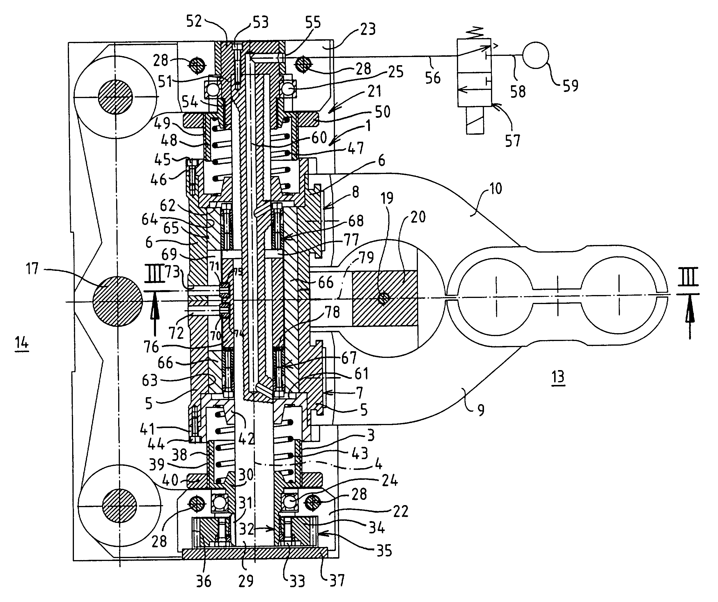
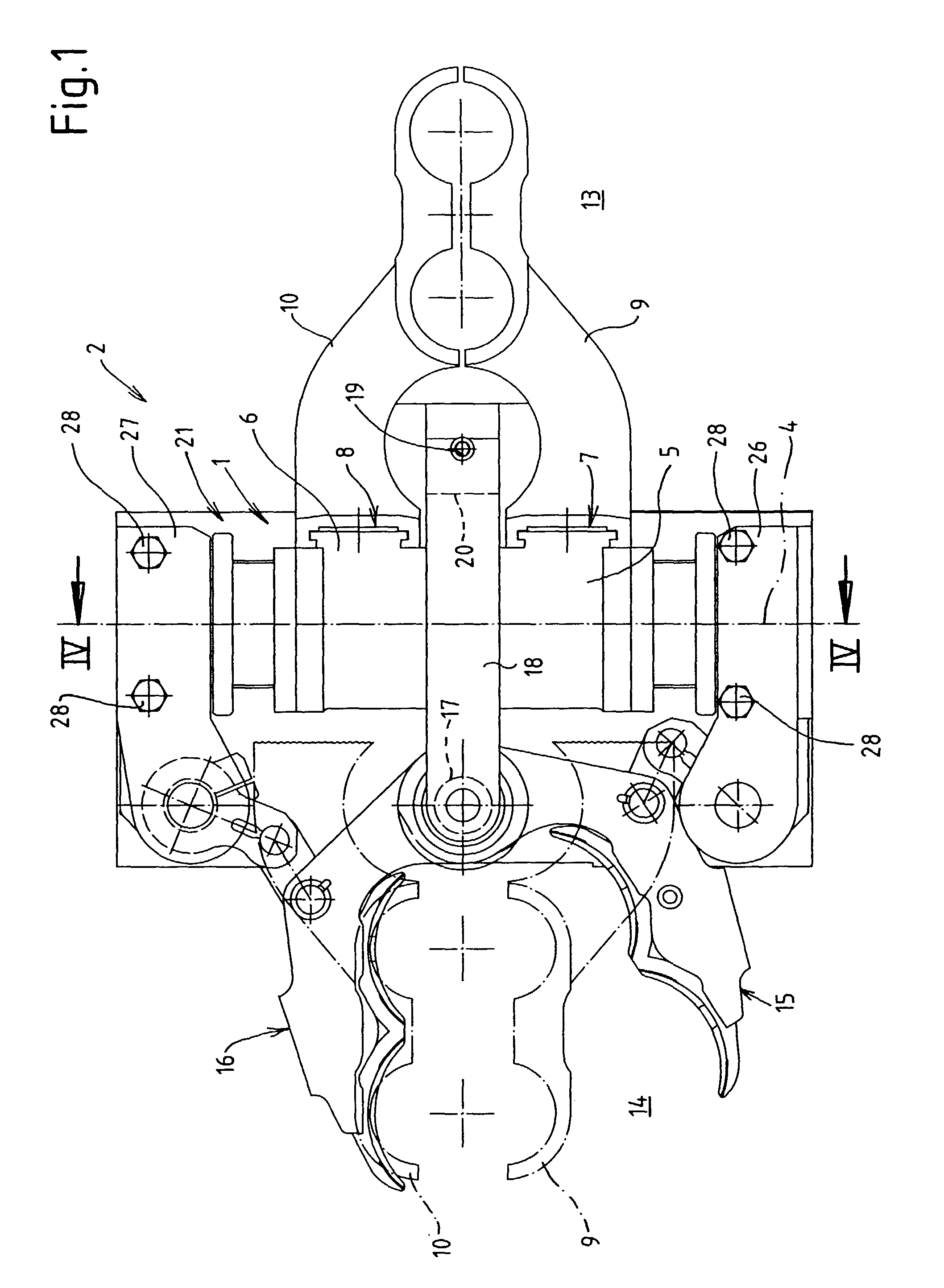
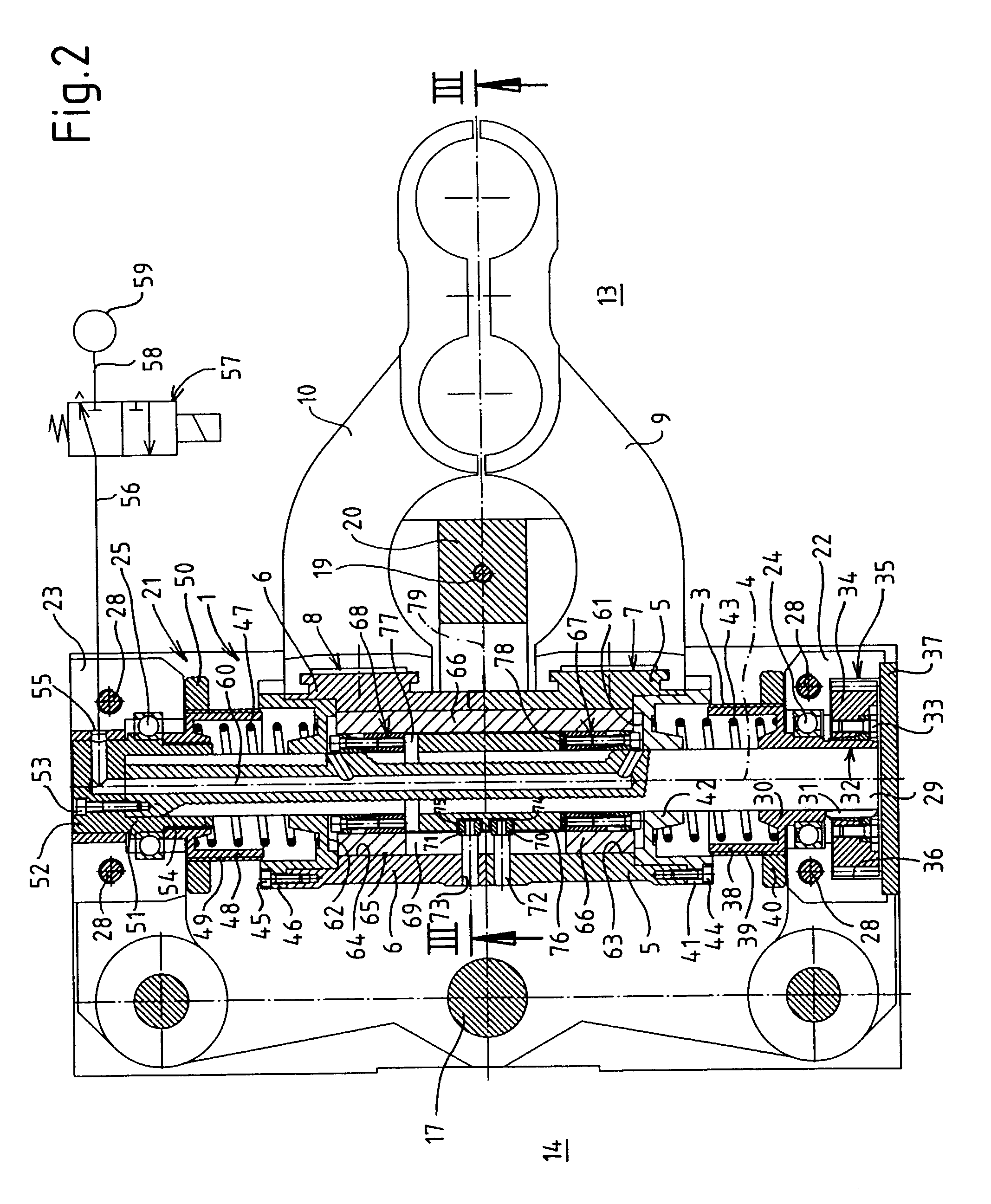
[0024]FIG. 1 shows an invert mechanism 1 for a glass forming machine 2, which can be, in particular, a section of an I.S. glass forming machine.

[0025]The invert mechanism 1 has an invert shaft 3 (FIG. 2) with a horizontal longitudinal axis 4. Guide sleeves 5 and 6 are connected to the invert shaft 3—in a way which will be described hereinunder—in a rotationally fixed manner but so as to be displaceable in the direction of the longitudinal axis 4. By means of a guide connection 7 and 8 each guide sleeve 5, 6 has a neck mold holder half 9 and 110 connected to it. In this example, the neck mold holder halves 9, 10 hold two neck molds 11 in a manner which is known per se, one of which neck molds is shown in FIG. 3.

[0026]In a manner which is known per se the neck molds 11 are rotated with parisons 12 held thereby (FIG. 3) by 180° about the longitudinal axis 4 out of a preforming station 13 of the glass forming machine 2 into a finishing forming station 14 of the glass forming machine 2. ...


PUM


Abstract

An invert mechanism for moving parisons between a pre-forming station and a finishing forming station of a glass forming machine is disclosed. The mechanism is disposed above a cover plate of a frame of the glass forming machine. An electric motor is disposed with its horizontal longitudinal axis above the cover plate. A driven shaft of the electric motor is connected to a horizontal invert shaft by means of a transmission. Between the driven shaft of the electric motor and the transmission a planetary gear is connected.

Description

FIELD OF THE INVENTION[0001]The invention relates to an invert mechanism for a glass forming machine for pre-forming and finishing parisons. The glass forming machine includes a frame box having a cover plate, a parision pre-forming station and a parison finishing forming station. The invert mechanism includes an invert shaft rotatably mounted on the glass forming machine above the cover plate. A neck mold holder is mounted on the invert shaft and is rotatable with the invert shaft in a reciprocating manner between the pre-forming and finishing forming stations. The invert shaft is rotated by an electric motor having a drive shaft with a longitudinal axis positioned above the cover plate. A transmission connects the drive shaft to the invert shaft.BACKGROUND OF THE INVENTION[0002]In a known invert mechanism of this type, as shown in Italian patent publication IT 1 247 203 B, FIG. 2, the electric servomotor is mounted with its vertical longitudinal axis below the cover plate of the b...

Claims


Application Information

Patent Timeline
IPC IPC(8): C03B11/16C03B9/00C03B9/16
CPCC03B9/165
Inventor SCHNEIDER, WILHELMWINKELHAKE, DIRKBOGERT, HERMANN
Owner HEYE HLDG
Why Eureka
Try Eureka