Optical differential pressure transducer utilizing a bellows and flexure system

a technology of optical differential pressure transducer and bellows, which is applied in the direction of fluid pressure measurement using elastically deformable gauges, instruments, mechanical elements, etc., can solve the problems of difficult to solve the flow measurement accuracy needed, the sensitiveness of optical sensors, and the inability of prior art differential pressure sensors to measure small differential pressures of interes

Inactive Publication Date: 2006-05-23
WEATHERFORD TECH HLDG LLC
View PDF15 Cites 44 Cited by
  • Summary
  • Abstract
  • Description
  • Claims
  • Application Information

AI Technical Summary

Benefits of technology

[0008]A pressure transducer that uses a rhomboidal flexure to provide displacement amplification to an optical sensing element is disclosed. The transducer includes an optical sensor disposed between sides of the flexure. The top portion of the flexure connects to a displacement device, such as a bellows. A first pressure port provides a first pressure to the bellows. A second pressure, preferably greater than the first pressure, is ported into a housing containing the flexure, which tends to compress the bellows and pull apart or expand the flexure. Such expansion pinches or compresses the optical sensing element between the sides of the flexure, and in particular stresses an optical sensing element containing a fiber Bragg grating. Assessing the Bragg reflection wavelength of the grating allows the differential pressure to be determined, although the transducer can also be used to sense an absolute pressure. A temperature compensation scheme, including the use of additional fiber Bragg gratings and thermal compensators axially positioned to counteract thermal effects of the optical sensing element, is also disclosed.

Problems solved by technology

However, this prior art differential pressure sensor may not be sensitive enough to measure small differential pressures of interest.
However, this pressure differential might in a given application be quite small, and therefore difficult to resolve with needed accuracy when performing flow measurements.
It is known that optical sensors are sensitive to temperatures, a point which can be deleterious when it is desired that the sensor only measure pressure effects.

Method used


Image

  • Optical differential pressure transducer utilizing a bellows and flexure system
  • Optical differential pressure transducer utilizing a bellows and flexure system
  • Optical differential pressure transducer utilizing a bellows and flexure system

Examples


Embodiment Construction

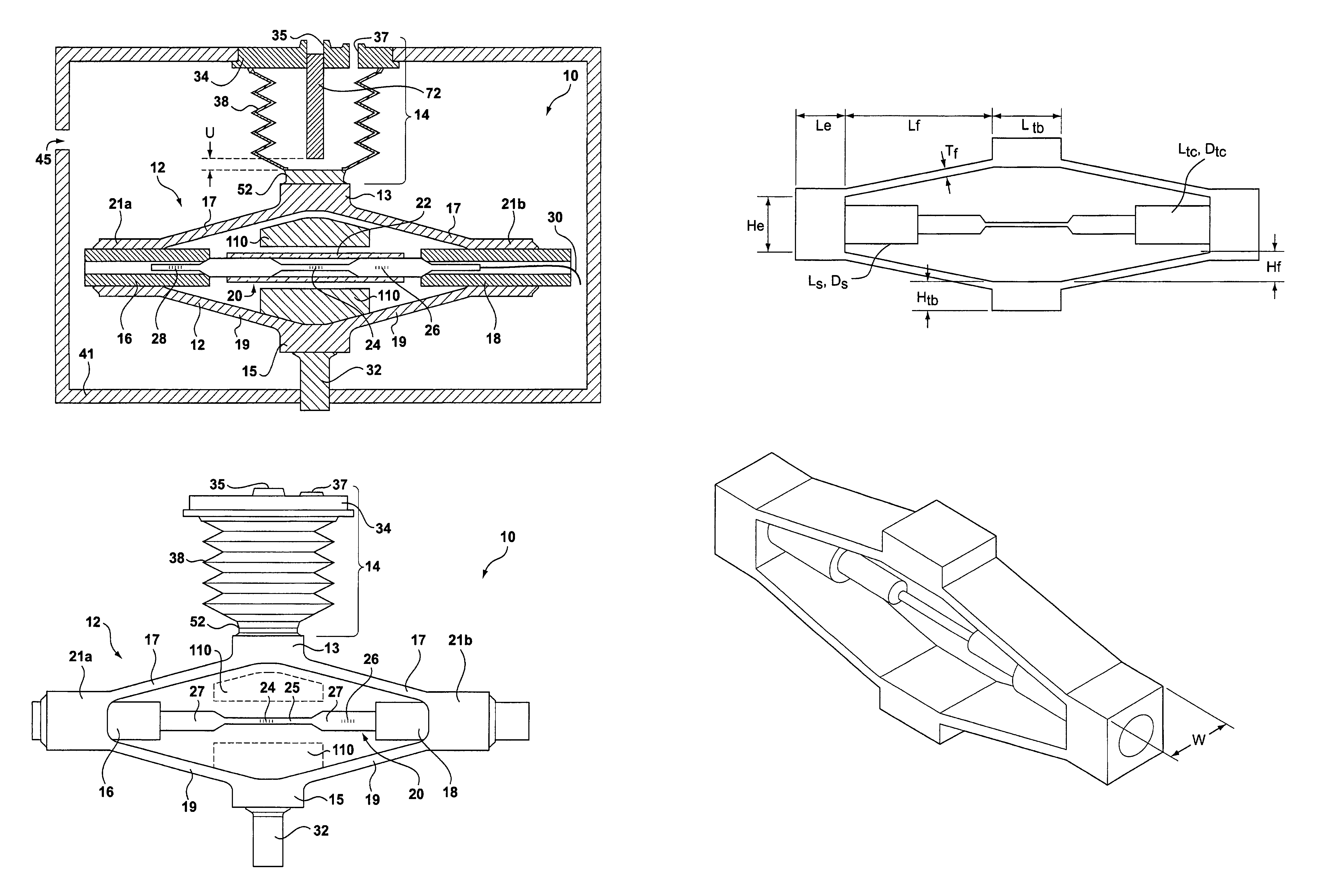
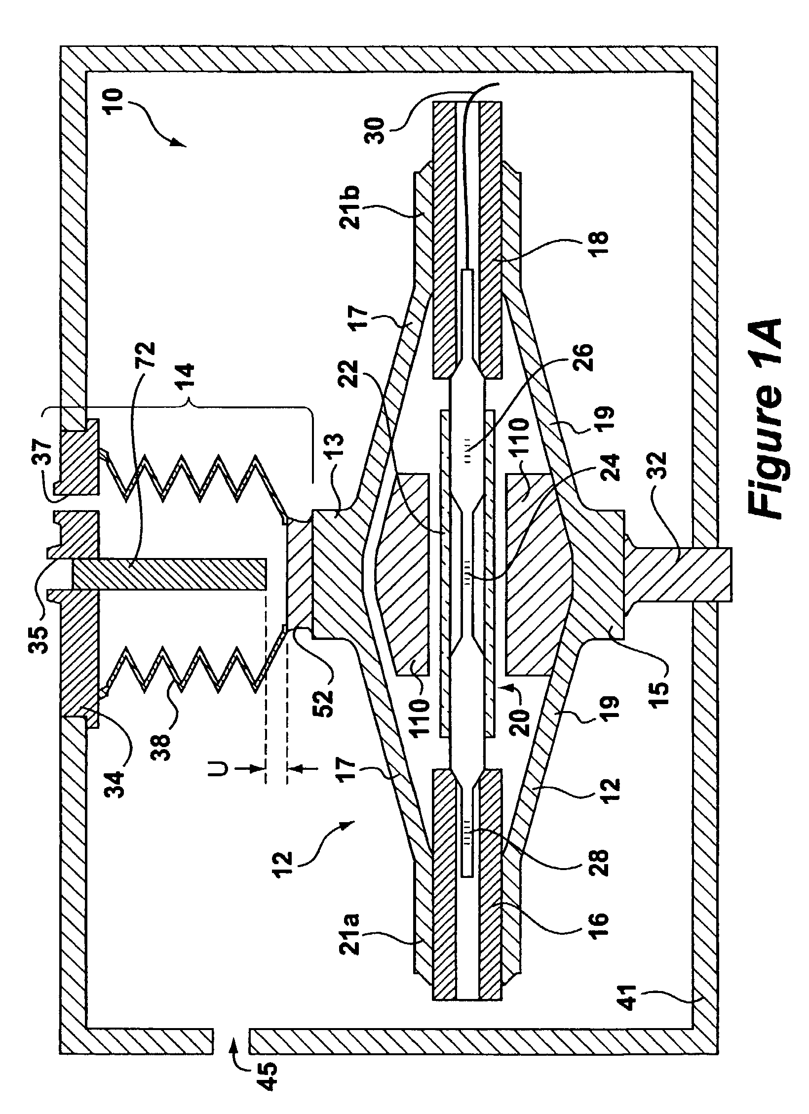
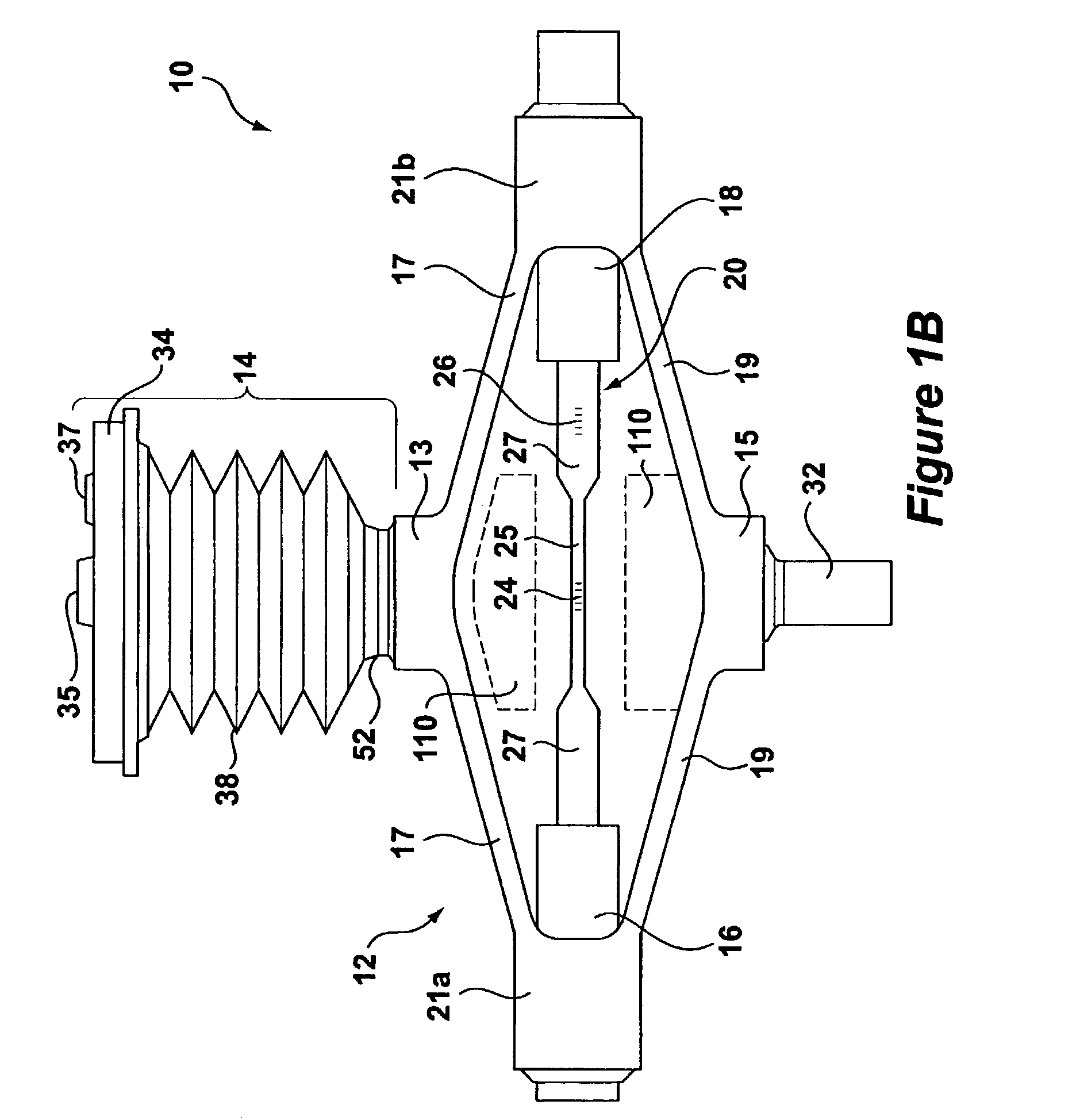
[0017]FIGS. 1A and 1B respectively disclose a differential pressure transducer 10 in a cross sectional and plan view. The basic components of the transducer 10 include a rhombus-shaped flexure element or spring 12, an optical sensing element 20 containing a pressure-sensitive FBG 24, and a displacement device 14 having a bellows 38. When used to sense a differential pressure, these components are housed in a housing 41 (not shown in FIG. 1B for clarity). Further details concerning the housing 41 are disclosed later in this disclosure, but at this point a simplified illustration and discussion are provided to illustrate the basic aspects of the invention. A disk 34 is coupled to the housing 41, and includes a centrally located hole 35 and a first porthole 37 that communicates with the inside of the bellows 38. The bottom 15 of the flexure 12 is affixed to the housing at securing pin 32. Housing 41 further contains a second porthole 45.

[0018]In operation, first and second pressures, w...


PUM

PropertyMeasurementUnit
heightaaaaaaaaaa
lengthaaaaaaaaaa
thicknessaaaaaaaaaa

Abstract

A pressure transducer that uses a rhomboidal flexure to provide displacement amplification to an optical sensing element is disclosed. The transducer includes an optical sensor disposed between sides of the flexure. The top portion of the flexure connects to a displacement device, such as a bellows. A first pressure port provides a first pressure to the bellows. A second pressure, preferably greater than the first pressure, is ported into a housing containing the flexure, which tends to compress the bellows and pull apart or expand the flexure. Such expansion pinches or compresses the optical sensing element between the sides of the flexure, and in particular stresses an optical sensing element containing a fiber Bragg grating. Assessing the Bragg reflection wavelength of the grating allows the differential pressure to be determined, although the transducer can also be used to sense an absolute pressure. A temperature compensation scheme, including the use of additional fiber Bragg gratings and thermal compensators axially positioned to counteract thermal effects of the optical sensing element, is also disclosed.

Description

CROSS REFERENCES TO RELATED APPLICATIONS[0001]U.S. Pat. No. 6,422,084, entitled “Bragg Grating Pressure Sensor,” contains subject matter related to that disclosed herein, and is incorporated herein by reference.TECHNICAL FIELD[0002]This invention relates to optical pressure sensors, and more particularly to a sensitive, temperature-compensated differential pressure transducer.BACKGROUND ART[0003]Optical sensors (or transducers) for the measurement of various physical parameters such as pressure and temperature often rely on the transmission of strain to a sensing element (e.g., a fiber Bragg grating (FBG) or a fiber optic coil). One such parameter that is highly desirable to measure in oil / gas well applications is differential pressure. With a differential pressure measurement, parameters such as phase fraction, phase fraction flow rate, bulk fluid flow rate, and fluid density can be directly calculated. Such measurements and methods for calculating these and other parameters using ...

Claims


Application Information

Patent Timeline
Patent Type & Authority Patents(United States)
IPC IPC(8): G01L7/06G01L9/00G01L11/02
CPCG01L11/025G01L9/0039
Inventor JONES, RICHARD TDUNPHY, JAMES R
Owner WEATHERFORD TECH HLDG LLC
Why Eureka
Try Eureka