Remote aiming system with video display

a remote control and video display technology, applied in the field of remote control aiming systems, can solve the problems of firearms not providing continuous or real-time feedback on the current point of aim, affecting the accuracy of aiming, and presenting special safety and operational difficulties for operators, etc., and achieve the effect of increasing the speed of positioning

Inactive Publication Date: 2006-05-23
PRECISION REMOTES
View PDF19 Cites 37 Cited by
  • Summary
  • Abstract
  • Description
  • Claims
  • Application Information

AI Technical Summary

Problems solved by technology

However, accuracy is often degraded when the user is unable to steady the device, when the operator experiences fatigue due in part to the physical stress of operating the device, by lack of fine control in the direction of aim (particularly when making quick gross changes of aiming position), and by a variety of responses the operator may make in response to hostile environments.
Portable firearms, such as semiautomatic rifles, present special safety and operational difficulties for their operators.
Because they emit single projectiles or discrete bursts of projectiles in a particular direction, rather than performing continuously, firearms do not provide continuous or real-time feedback on the current point of aim.
Furthermore, because firearms impart significant inertia into their projectiles, the corresponding recoil may overcome the operator's capacity to steady the firearm steady while firing.
The recoil thus causes a slight or gross change in the direction of aim following firing, requiring re-aiming of the firearm after each projectile or round of projectiles, creating a corresponding limits to the fine control of aim that would otherwise be obtainable by iterative re-aiming.
Furthermore, combat situations typically encountered by police or light infantry soldiers involve substantial physical danger for the operator, who must take defensive steps to avoid injury.
Such steps greatly increase the training time required to learn how to use a firearm in hostile environments, and severely reduce the aiming accuracy and firing frequency.
Despite the advantages noted, several critical limitations prevent remotely-controlled aiming mechanisms from achieving the desired improvements in accuracy and safety, and consequently such mechanisms have not gained widespread acceptance.
First, there is a trade-off between speed and precision of operation in the positioning means.
A mechanism capable of fine adjustments to aiming position is usually not capable of making quick gross movements.
Mechanisms that can make quick gross movements are usually not capable of fine control.
Even when a single device is capable of both rapid gross movements and precise fine control, the gross movements generally achieve only an approximate aiming position, after which fine positioning control must be accomplished, greatly reducing the speed of re-aiming the device following a gross movement or correction.
Second, limitations in eye-hand coordination, muscle control, and perception, generally prevent operators from achieving the precision, speed, or accuracy of aiming movements with a hand remote controller that they could achieve by direct manipulation of a device.
Whereas operators can generally manipulate devices quickly to a new point of aim by handling the device, after a minimum of practical training, most operators are unable to operate hand control devices such as joysticks or trackballs with enough control of speed or direction to achieve comparable results.
Third, delays inherent to remote control systems cause operators to overcompensate when making a change in aiming location, thus overshooting their intended target direction.
One such delay is mechanical, caused by inertial and other delays in the means of mechanically positioning devices.
Another delay is the perceptual lag between the time that an aiming location is achieved and reported (via direct observation or a video signal, for example), and the time the operator becomes aware of and responds to the observed location.

Method used


Image

  • Remote aiming system with video display
  • Remote aiming system with video display
  • Remote aiming system with video display

Examples


Embodiment Construction

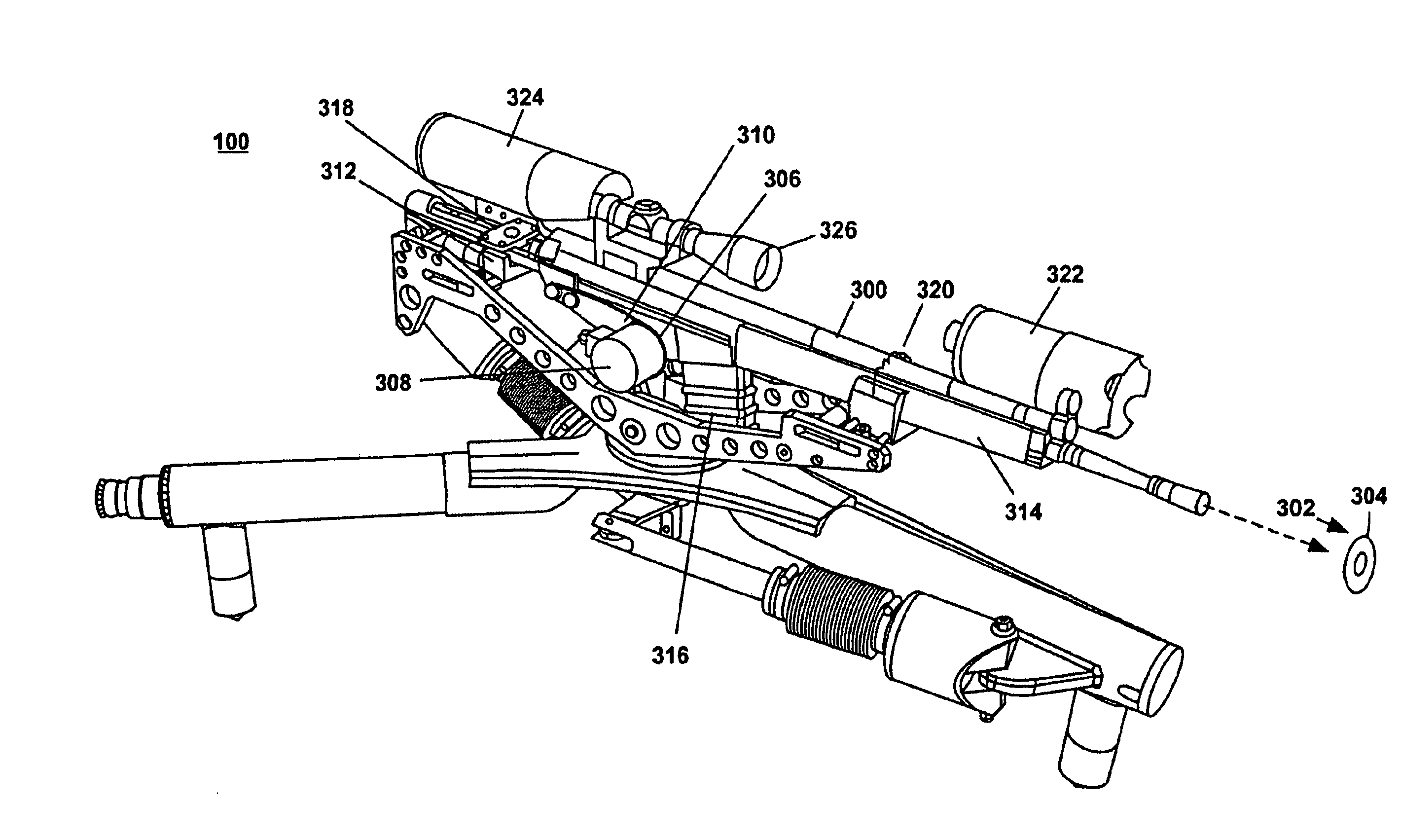
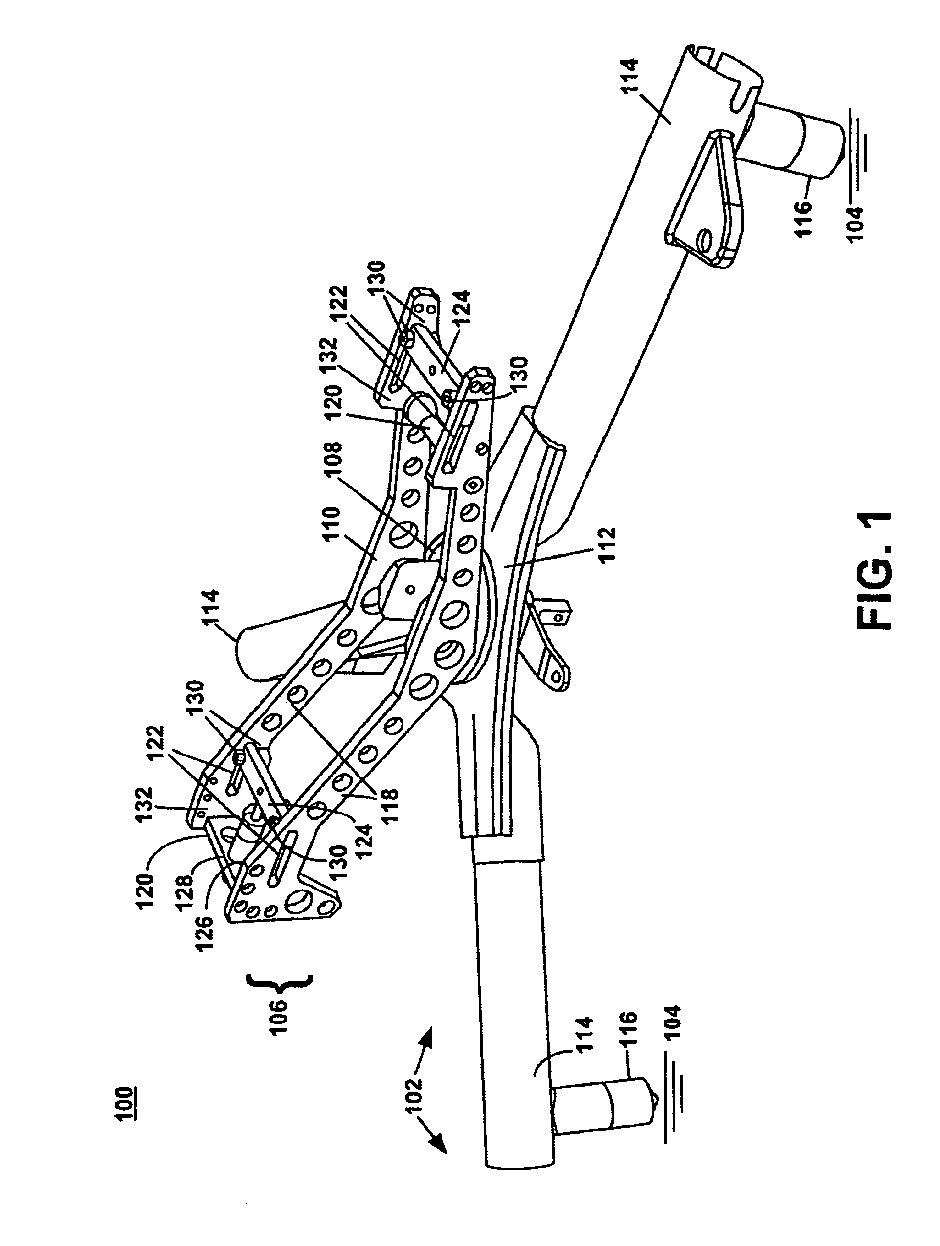
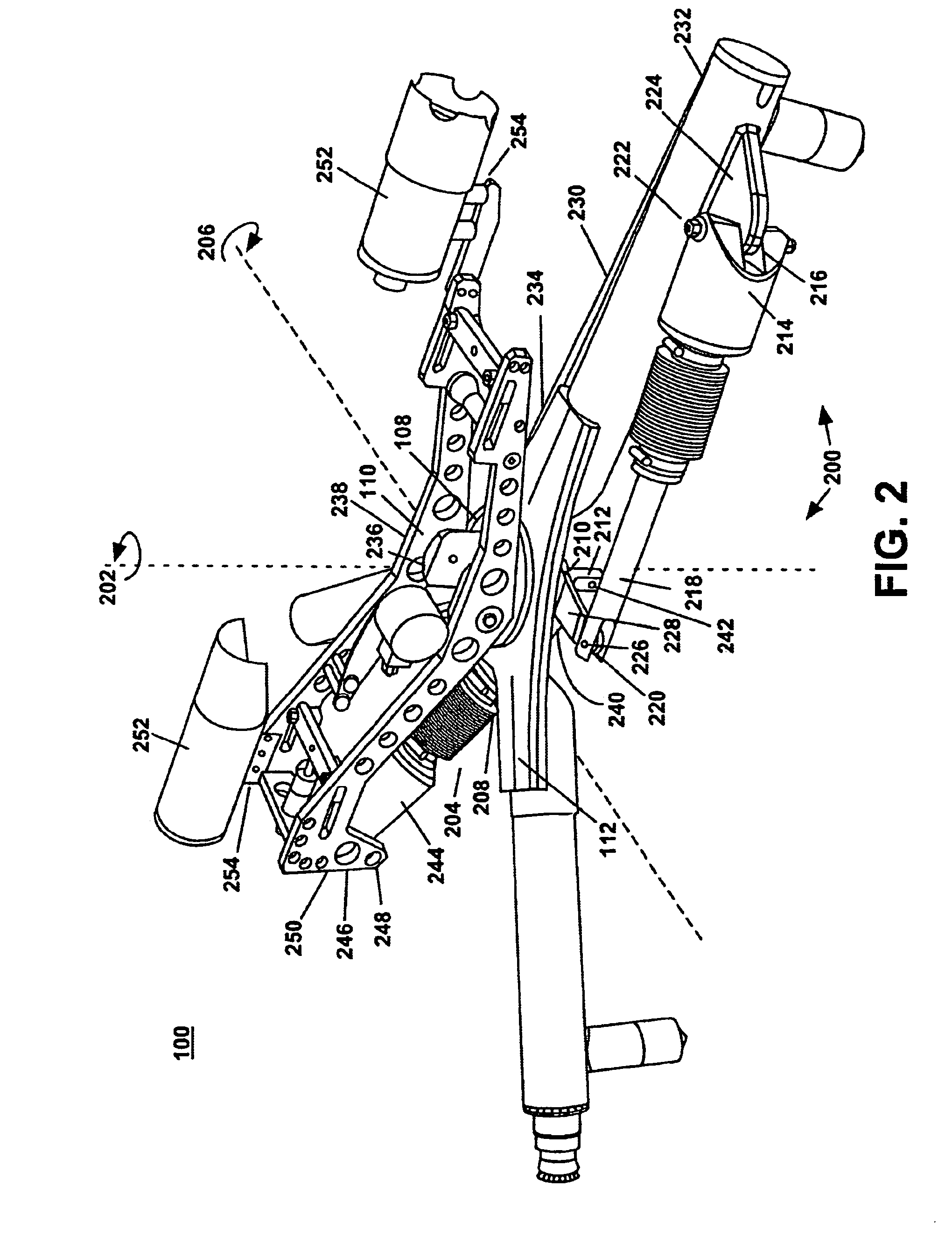
[0028]Reference will now be made in detail to the described embodiment of the invention, so as to enable a person skilled in the art to make and use the invention in the context of a particular application and its applications, namely that of aiming a firearm. It is understood that this example is not intended to limit the invention to one preferred embodiment or application. On the contrary, it is intended to cover alternatives, modifications, and equivalents. Various modifications to the present invention will be readily apparent to one of ordinary skill in the art, and can be made to the described embodiment within the spirit and scope of the invention as defined by the appended claims.

[0029]For a better understanding, components of the described embodiment are labeled with three-digit component numbers, the first digit of which corresponds to the first figure in which such component appears and is labeled. Like components are designated by like reference numerals throughout the ...


PUM


Abstract

The present invention provides a powered aiming platform for pointing devices such as firearms, illumination devices, or sensing instruments, remotely controlled by a hand-controller device, with video feedback of the aiming position and audio feedback of the exact direction and speed of positioning movements. The present invention overcomes the safety and accuracy limitations of manual and conventional remotely-controlled aiming mechanisms, thereby allowing operators to point devices accurately and quickly with predictable, precise control. In the case of firearms, the present invention maintains a steady position after repeated firing.

Description

CROSS-REFERENCE TO RELATED APPLICATIONS[0001]This application is a continuation of application Ser. No. 09 / 861,087 filed May 18, 2001 which is now U.S. Pat. No. 6,679,158, which is a divisional of application Ser. No. 09 / 084,788 filed May 21, 1998 which is now U.S. Pat. No. 6,237,462.BACKGROUND OF THE INVENTION[0002]1. Field of the Invention[0003]The present invention relates generally to aiming systems, and specifically to portable remotely-controlled aiming mechanisms for pointing firearms and other devices at an intended target, as well as video feedback components of such systems indicating the direction of aim, and audio feedback components indicating changes in the direction of aim.[0004]2. Description of Related Art[0005]The typical means for aiming small portable devices such as firearms, optical instruments, cameras, and spotlights, is for a human operator to aim the device by hand in the direction of the intended target, while physically supporting the device. Control feed...

Claims


Application Information

Patent Timeline
Patent Type & Authority Patents(United States)
IPC IPC(8): F41A23/00F41G5/06
CPCF41A23/12F41A23/14F41A27/22F41A27/24F41G5/06F41A27/28F41G1/00F41G3/165F41A27/26
Inventor HAWKES, GRAHAM S.KONVALIN, HOWARD F.
Owner PRECISION REMOTES
Why Eureka
Try Eureka