Low emission fuel for use with controlled temperature combustion, direct injection, compression ignition engines

a technology of low emission fuel and combustion chamber, which is applied in the direction of machines/engines, electrical control, mechanical equipment, etc., can solve the problems of poor combustion, higher levels of harmful emissions, and low cetane fuels that have not been accepted in the market, so as to reduce nox formation and reduce smoke/pm formation

Inactive Publication Date: 2006-05-23
ENVIRONMENTAL PROTECTION AGENCY US
View PDF9 Cites 26 Cited by
  • Summary
  • Abstract
  • Description
  • Claims
  • Application Information

AI Technical Summary

Benefits of technology

[0016]Applicant has found that use of a fuel with a substantially lower cetane number than conventional diesel fuel effectuates a significant reduction in smoke/PM formation in direct injection compression ignition engines of the type disclosed in the parent applications hereto. In a preferred embodiment, an FCC Naptha fu...

Problems solved by technology

However, low cetane fuels have not been accepted in the market to date.
Attempts to use low cetane fuel formulations in conjunction with conventional ...

Method used


Image

  • Low emission fuel for use with controlled temperature combustion, direct injection, compression ignition engines
  • Low emission fuel for use with controlled temperature combustion, direct injection, compression ignition engines
  • Low emission fuel for use with controlled temperature combustion, direct injection, compression ignition engines

Examples


Embodiment Construction

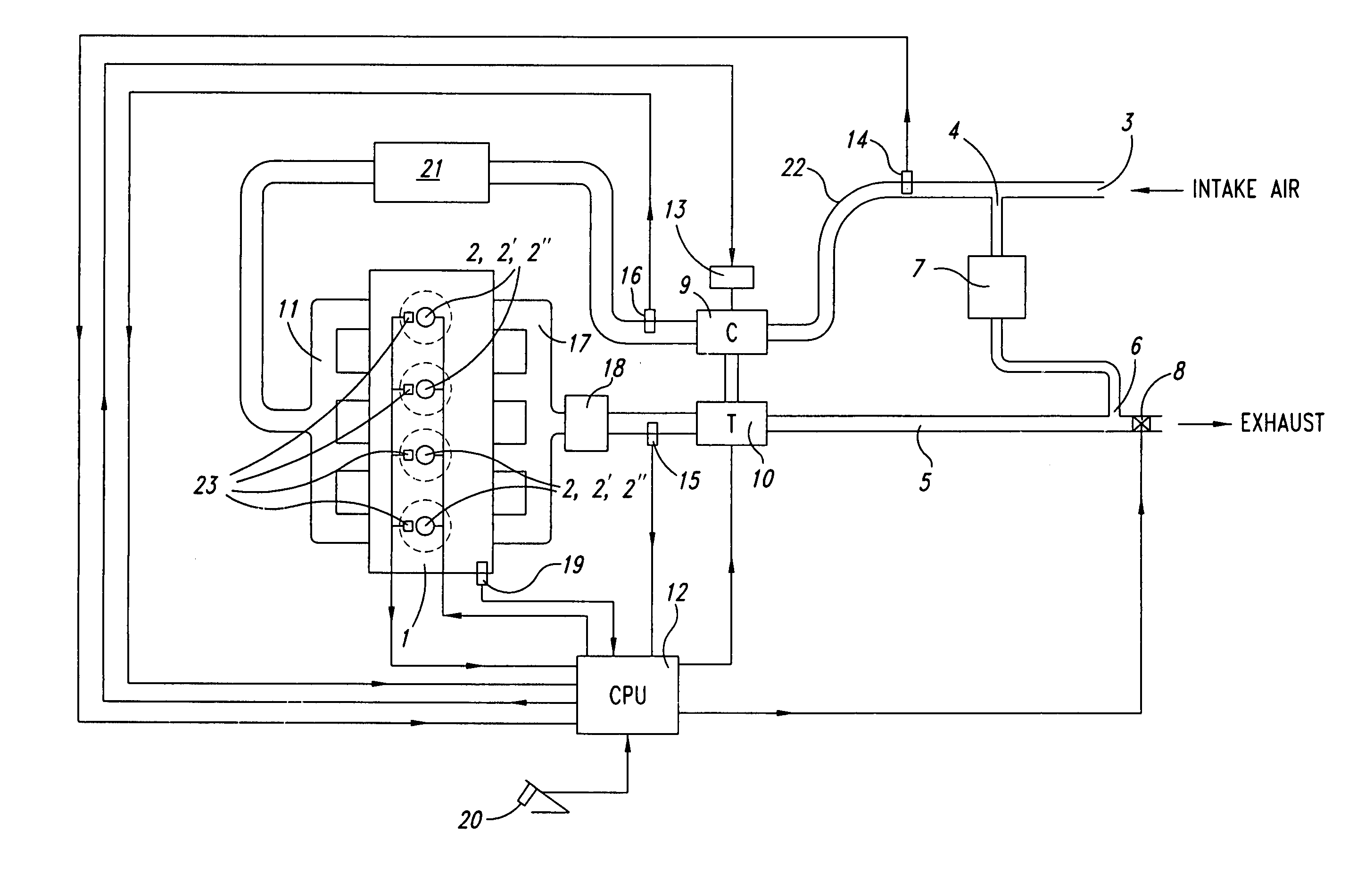
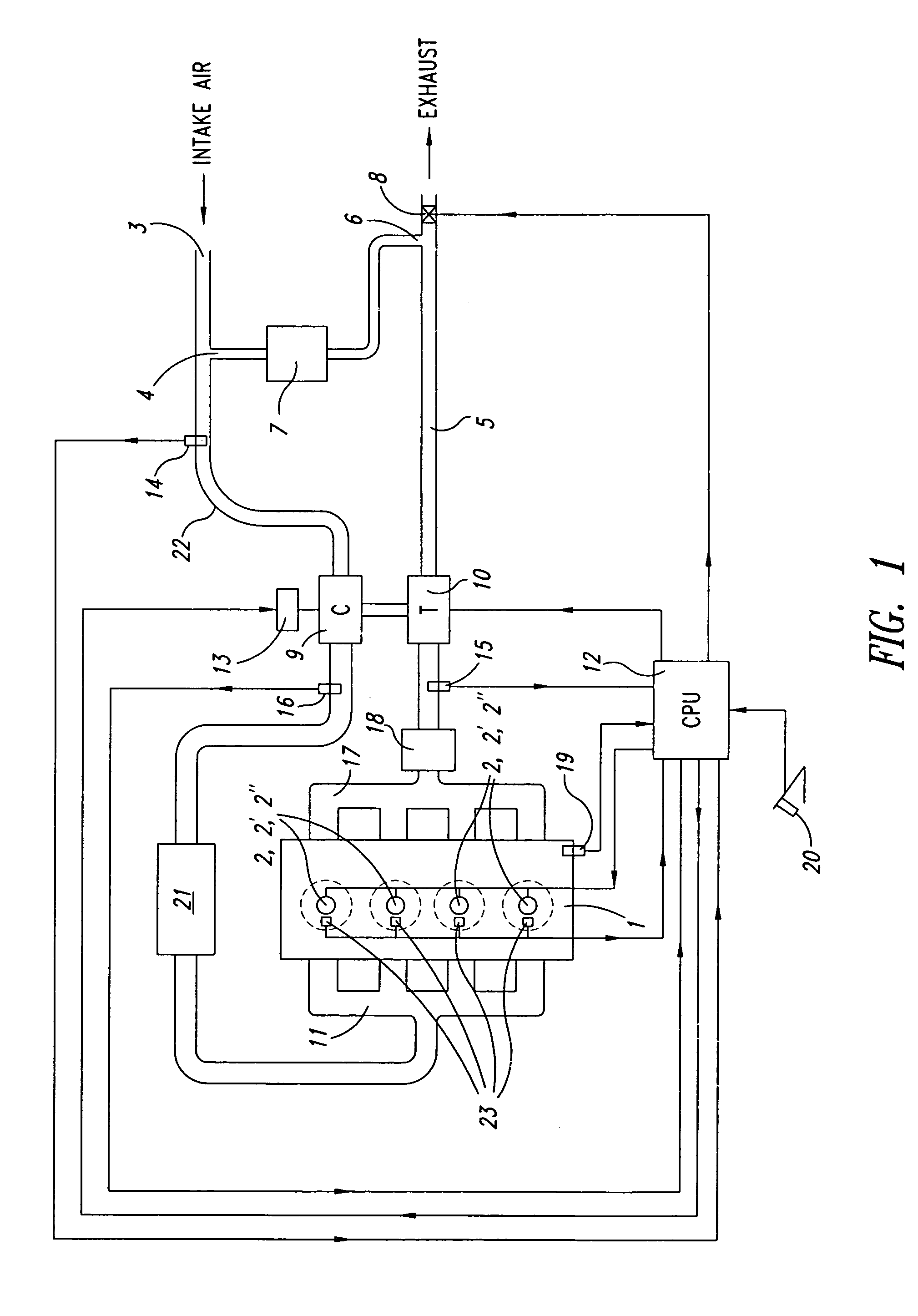
[0020]A preferred controlled temperature combustion, direct injection, compression ignition engine system for use with the present invention is schematically presented in FIG. 1. Referring to FIG. 1, the air handling system for engine 1 will first be explained. Ambient air enters an air intake line 22 for the system at port 3. A portion of exhaust gas in exhaust line 5 of the system is routed from the exhaust line 5 at port 6 through exhaust gas cooler 7 to port 4, where the recirculated exhaust gas blends with the ambient air at port 4, thereby forming a charge-air mixture in the air intake line 22. EGR control valve 8 is located just downstream of port 6 in exhaust line 5. By restricting flow through valve 8, exhaust gas flow rate through port 6 is adjusted, and oxygen concentration of the charge-air mixture may be determined and controlled, as will be discussed later.

[0021]The combined ambient air and recirculated exhaust gas (collectively “charge-air”) flows through the intake a...


PUM


Abstract

A low emission, direct injection, compression ignition, internal combustion engine operates with reduced charge-air oxygen concentration levels to control localized peak combustion temperatures and reduce NOx formation. Low cetane fuel, below 43 cetane, and most preferably with a cetane rating below 30, is utilized with the combustion system to reduce smoke and PM formation simultaneously with the reduced NOx formation. In a preferred embodiment, FCC Naptha fuel, with a cetane rating below 30 and an end boiling point below 120 degrees Celsius, is used with the combustion system together with the reduced charge-air oxygen concentration levels to produce engine-out NOx emissions of 0.2 g/bhp-hr or lower, and PM emissions at 0.01 g/bhp-hr or lower, without the need for NOx (and potentially PM) aftertreatment. Potential commercial applications of the fuel and combustion system are discussed, including application to vehicle fleets, with novel methods of operating a vehicle fleet (and of providing fuel to such fleets) to meet motor vehicle emissions regulations at a reduced cost also being disclosed.

Description

CROSS REFERENCE TO RELATED APPLICATIONS[0001]This application is a continuation-in-part of U.S. patent application Ser. No. 10 / 666,678, filed Sep. 19, 2003, now issued as U.S. Pat. No. 6,857,263, which application is a continuation-in-part of Ser. No. 10 / 214,229, filed Aug. 8, 2002 now-issued U.S. Pat. No. 6,651,432, “Controlled Temperature Combustion Engine”, issued Nov. 25, 2003, both of which related applications are incorporated herein by refercnce in their entirety.BACKGROUND OF THE INVENTION[0002]1. Field of the Invention[0003]The present invention relates to a fuel, and methods, for reducing harmful emissions, particularly engine-out smoke / PM levels, from engines of the direct injection compression ignition type, particularly diesel engines. The present invention also relates to methods of operating vehicle fleets, or providing fuel to vehicle fleets, to meet motor vehicle emissions regulations at a reduced cost.[0004]2. Background of the Invention[0005]The continuing use of ...

Claims


Application Information

Patent Timeline
IPC IPC(8): F02D41/04F02M25/07F01N3/10F01N3/035F01N13/02F02B1/12F02B37/007F02B37/013F02B37/10F02B37/14F02B39/10F02D35/02F02D41/00F02D41/14
CPCF01N3/035F02B1/12F02B29/04F02B37/10F02B37/14F02B39/10F02D35/025F02D41/0007F02D41/144F02D41/1497F02M25/0709F02M25/0713F02M25/0718F02M25/0754F02M25/0755F02D19/061F02D19/0649F02D19/0689F02D41/3035F02D35/028F01N13/009Y02T10/36F02D41/0052F02D41/1454F02D2200/0406F02D2200/0612F02D2200/602F02M25/0711F02M2200/95Y02T10/146Y02T10/144F01N2430/06F02M26/46F02M26/06F02M26/08F02M26/10F02M26/15F02M26/47Y02T10/12Y02T10/30
Inventor GRAY, JR., CHARLES L.
Owner ENVIRONMENTAL PROTECTION AGENCY US
Why Eureka
Try Eureka