Combustion method and internal combustion engine

a combustion engine and combustion method technology, applied in combustion engines, machines/engines, pistons, etc., can solve the problems that the soot emissions in particular cannot be reduced to the desired degree compared to conventional diesel combustion, and achieve the effect of stabilizing the deflection

Active Publication Date: 2016-10-25
DAIMLER AG
View PDF27 Cites 6 Cited by
  • Summary
  • Abstract
  • Description
  • Claims
  • Application Information

AI Technical Summary

Benefits of technology

[0003]Since the combustion fronts make effective use of the available space in the combustion chamber, the known combustion process utilizes to a great extent the fresh gas or fresh gas-exhaust gas mixture that is available in the combustion chamber, which significantly reduces the soot formation during the combustion. In addition, due to the combustion of the third combustion front in a time-delayed manner compared to the first two combustion fronts, local peak temperatures are lowered, thus reducing NOx formation.
[0027]An elongated, relatively narrow, lobe-shaped injection jet having a high propagation rate may advantageously be generated by means of the conical injection holes, so that the injection jet spreads out only slightly in the combustion chamber, and the injection jet may thus strike the jet divider contour with high momentum.

Problems solved by technology

However, in the known combustion process, only a small time window or only a small crank angle is available for dividing the injection jets at the jet divider contour into optimally dimensioned three partial quantities, so that optimal conditions for forming the third combustion front are present in only a few load and speed ranges, as the result of which the soot emissions in particular cannot be reduced to the desired degree compared to conventional diesel combustion.

Method used


Image

  • Combustion method and internal combustion engine
  • Combustion method and internal combustion engine
  • Combustion method and internal combustion engine

Examples


Embodiment Construction

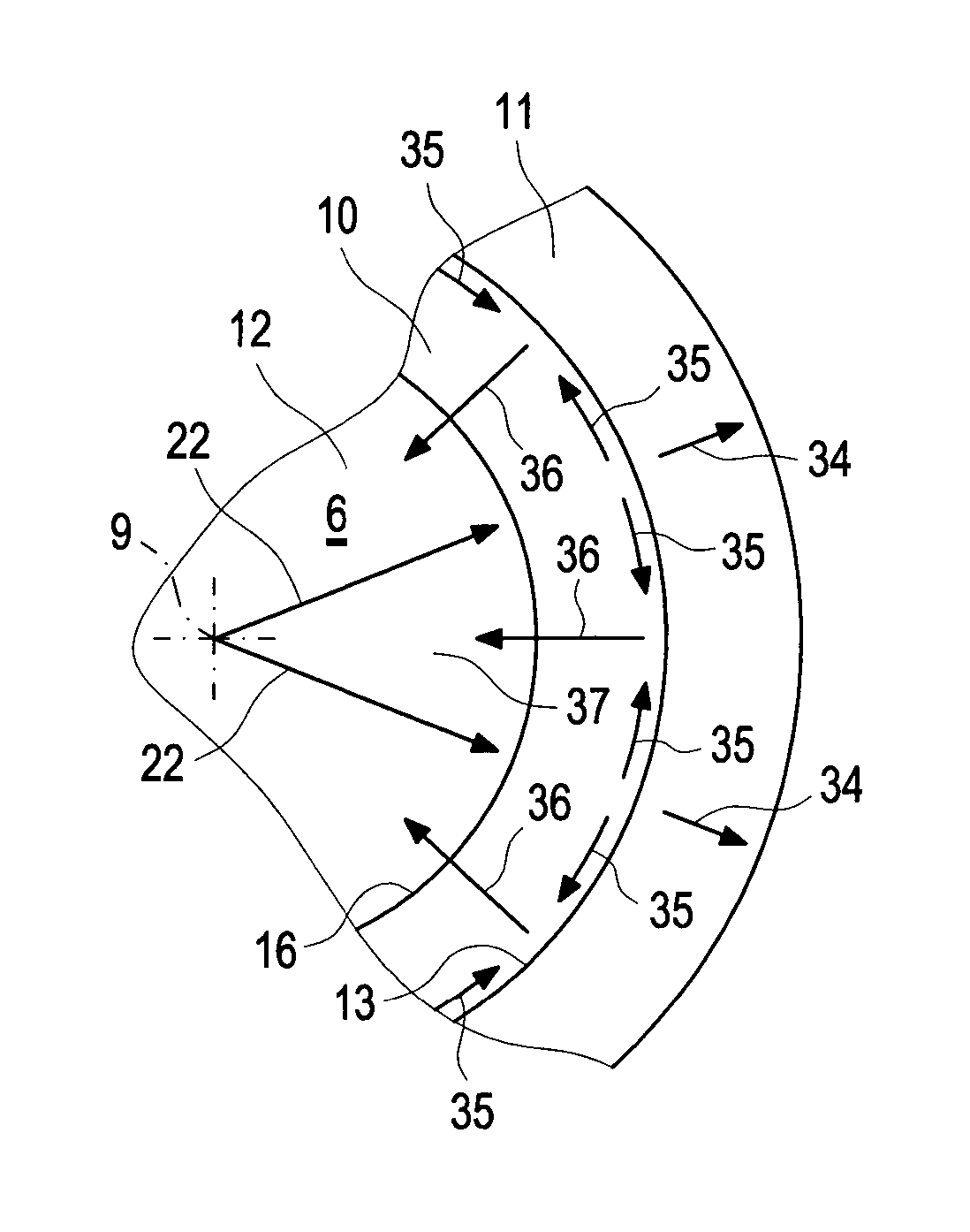
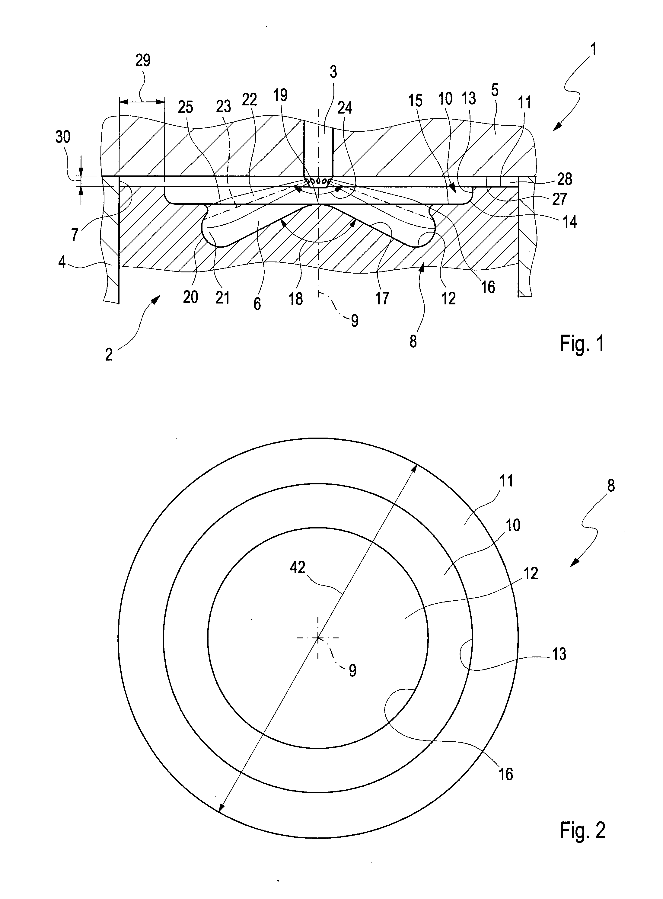
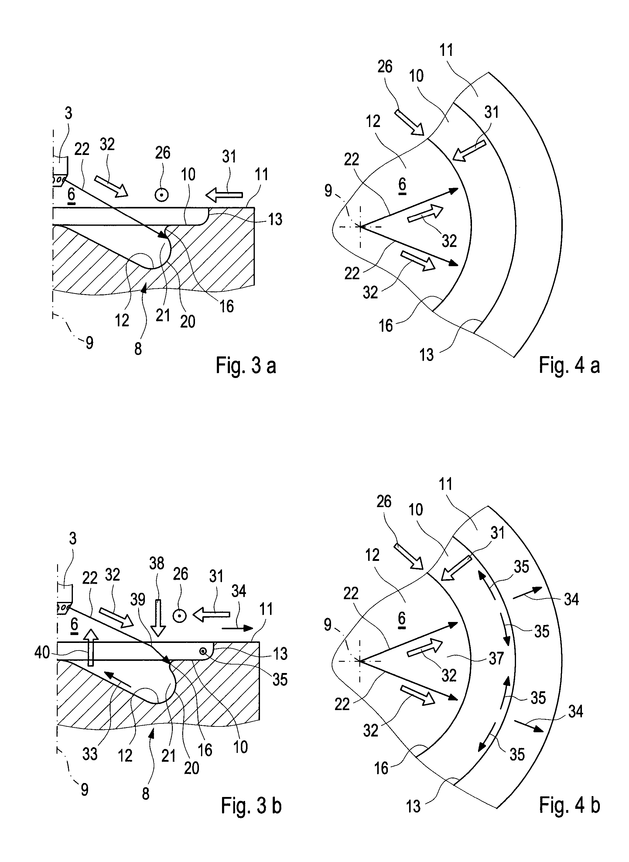
[0038]According to FIG. 1, an internal combustion engine 1, which in particular may be used in a motor vehicle, specifically, in a utility vehicle or also a passenger vehicle, includes at least one cylinder 2 and one injection nozzle 3 of an injector, not illustrated in greater detail, per cylinder 2. The internal combustion engine 1 is illustrated in FIG. 1 only in the region of such a cylinder 2. In principle, the internal combustion engine 1 may also have more than one cylinder 2. The particular cylinder 2 is provided in a crankcase 4 on which a cylinder head 5 is situated in a customary manner.

[0039]In the particular cylinder 2, a combustion chamber 6 is laterally delimited by a cylinder wall 7, and is delimited axially on the one hand by the cylinder head 5 and axially on the other hand by a piston 8 situated in the cylinder 2 in an adjustable-stroke manner. The cylindrical cylinder wall 7 defines a longitudinal center axis 9 of the cylinder 2. In the example, the injection noz...


PUM


Abstract

A combustion process with auto-ignition for direct-injection internal combustion engines involves dividing injection jets at a jet divider contour into a first partial quantity, a second partial quantity, and third partial quantities. The first partial quantity enters into the piston cavity, the second partial quantity enters via the piston step into a region between the piston crown and the cylinder head, and the third partial quantities, starting from the respective injection jet, spread out on both sides in the peripheral direction in opposite directions along the piston step, and the respective third partial quantities collide with one another between two adjacent injection jets within the piston step and are deflected radially inwardly. The first partial quantity and the second partial quantity form a first combustion front and a second combustion front, and the partial quantities which in each case are jointly deflected inwardly form a third combustion front radially inwardly into a gap between the injection jets. The injection jets are deflected upstream from the jet divider contour in the direction of the piston by means of a resultant flow formed essentially from a swirl, a squish gap flow, and a jet flow.

Description

BACKGROUND AND SUMMARY OF THE INVENTION[0001]Exemplary embodiments of the present invention relate to a combustion process with auto-ignition for direct-injection internal combustion engines and to an internal combustion engine, in particular for a motor vehicle, for carrying out such a combustion process.[0002]German patent document DE 10 2006 020 642 A1 discloses an auto-ignition internal combustion engine for implementing a combustion process in which the internal combustion engine has at least one cylinder whose combustion chamber is laterally delimited by a cylinder wall, and is delimited axially on the one hand by a cylinder head, and axially on the other hand by an adjustable-stroke piston in the cylinder. The cylinder wall defines a longitudinal center axis of the cylinder. In addition, the internal combustion engine includes one injection nozzle per cylinder which is situated coaxially with respect to the combustion chamber, i.e., situated in the cylinder head essentially c...

Claims


Application Information

Patent Timeline
Patent Type & Authority Patents(United States)
IPC IPC(8): F02F3/28F02B17/00F02B23/06
CPCF02B17/005F02B23/0651Y02T10/125F02B23/0693F02B23/0621Y02T10/12
Inventor ZOELLER, HERBERTSEDDOUK, NAIMA
Owner DAIMLER AG
Why Eureka
Try Eureka