Control apparatus and control method for internal combustion engine

a control apparatus and control method technology, applied in the direction of electric control, ignition automatic control, machines/engines, etc., can solve the problems of excessively rich air-fuel mixture in the combustion chamber, increase in the effective lifetime of the components of the exhaust system, and increase in the temperature of the exhaust gas in the gasoline engine, so as to prevent the occurrence of misfire and prevent overheating the exhaust system

Inactive Publication Date: 2006-05-23
TOYOTA JIDOSHA KK
View PDF7 Cites 57 Cited by
  • Summary
  • Abstract
  • Description
  • Claims
  • Application Information

AI Technical Summary

Benefits of technology

[0014]In view of the above problems, it is one object of the invention to provide a control apparatus and control method for an internal combustion engine, which makes it possible to prevent (or at least reduces the possibility of) an excessive increase in an exhaust system temperature while preventing occurrence of a misfire due to a rich air-fuel ratio in an internal combustion engine in which ignition timing is retarded, even when a low-octane fuel is used.
[0016]In the first aspect of the invention, the supply of the fuel to the engine is stopped when the value of a parameter relating to a misfire of the engine, such as an amount of the fuel supplied to the engine, an engine intake air amount, and ignition timing, satisfies the misfire condition. In the first aspect of the invention, for example, the supply of the fuel to the engine may be stopped when the value of the parameter has reached a limit value corresponding to the misfire condition. The limit value of the parameter corresponding to the misfire condition varies depending on the octane value of the fuel. Accordingly, in the first aspect of the invention, the controller may change the limit value of the parameter based on the octane value of the fuel. In this case, since the limit value of the parameter is changed based on the octane value of the fuel, it is possible to prevent an excessive increase in an exhaust system temperature by suppressing an increase in an exhaust gas temperature without causing a misfire even when the octane value of the fuel is changed.
[0018]In the second aspect of the invention, in the case where an increase in an exhaust system temperature is suppressed by increasing the amount of the fuel supplied to the engine, it is determined whether a misfire may occur if the engine is supplied with the fuel of the amount required for maintaining the exhaust system temperature at or below an upper limit temperature. When it is determined that a misfire may occur, the supply of the fuel to the engine is stopped. Thus, in the case where the octane value of the fuel is low, and the amount of the fuel supplied to the engine needs to be increased by a large amount in order to suppress the increase in the exhaust system temperature, fuel cut is performed. Accordingly, it is possible to prevent overheating of the exhaust system while preventing occurrence of a misfire.
[0019]According to a third aspect of the invention, a control apparatus for an internal combustion engine includes a controller that retards ignition timing of the engine, and increases an amount of a fuel supplied to the engine based on a retard amount of the ignition timing. The controller calculates a maximum engine intake air amount at which an exhaust system temperature can be maintained at or below a predetermined upper limit temperature by increasing the amount of the fuel supplied to the engine without causing a misfire of the engine, and limits an engine intake air amount to a value no greater than the maximum engine intake air amount.
[0021]Accordingly, in the third aspect of the invention, the engine intake air amount is prevented from exceeding the maximum engine intake air amount at which the exhaust system temperature can be maintained at or below the predetermined upper limit temperature by increasing the amount of the fuel supplied to the engine without causing a misfire of the engine. Thus, it is possible to prevent overheating of the exhaust system while preventing occurrence of a misfire.

Problems solved by technology

However, as the ignition timing is retarded, an exhaust gas temperature increases in the gasoline engine.
Therefore, when the ignition timing is retarded in order to prevent occurrence of knocking as described above, the temperature of components of an exhaust system may excessively increase due to an increase in the exhaust gas temperature during high-load operation or the like, which may lead to a decrease in the effective lifetime of the components of the exhaust system.
However, in the case where the fuel injection amount is increased by a larger amount in order to suppress the increase in the exhaust system temperature as the octane value of the fuel is lower, an air-fuel mixture in a combustion chamber may become excessively rich and a misfire limit may be reached.
Accordingly, in the case where the increase in the exhaust system temperature is suppressed by increasing the fuel injection amount during the high-load operation or the like and when the octane value is lowest, the fuel injection amount needs to be increased by a large amount, which may lead to occurrence of a misfire in a combustion chamber due to a rich air-fuel ratio.

Method used


Image

  • Control apparatus and control method for internal combustion engine
  • Control apparatus and control method for internal combustion engine
  • Control apparatus and control method for internal combustion engine

Examples


first embodiment

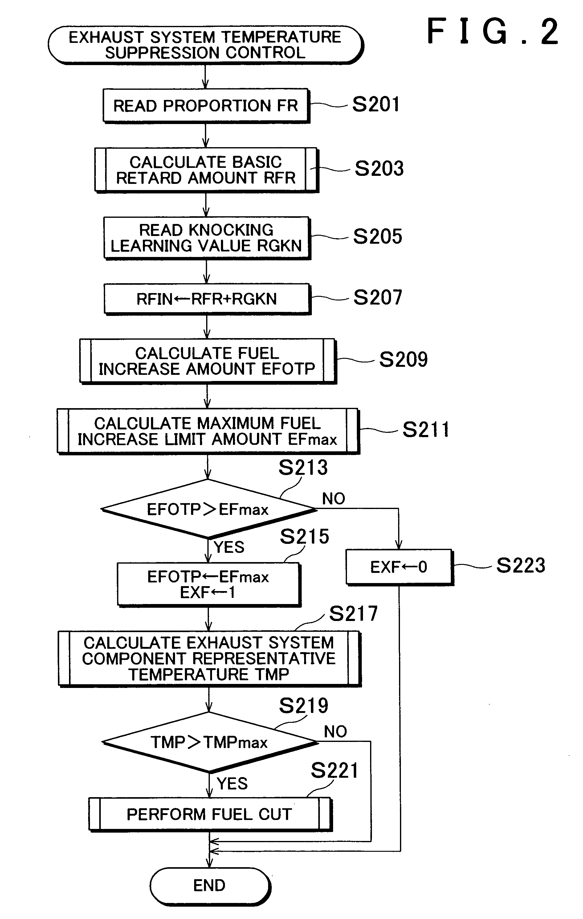
[0049]In a first embodiment, it is determined whether a misfire may occur in the engine if the fuel supply amount is increased in order to suppress the increase in the exhaust system temperature. When it is determined that a misfire may occur, fuel cut is performed so that the exhaust system temperature is decreased without increasing the fuel supply amount.

[0050]In other words, every time the engine is operated in an engine operating region in which a misfire may occur if the fuel supply amount is increased in order to suppress the increase in the exhaust system temperature, the fuel cut is performed. As a result, the engine is prevented from being operated in the aforementioned region. Therefore, it becomes possible to maintain the exhaust system temperature at or below the upper limit temperature without causing a misfire in the engine due to a rich air-fuel ratio.

[0051]FIG. 2 is a flow chart explaining the operation of the aforementioned control for suppressing the increase in t...

third embodiment

[0080]That is, in this embodiment as well, when the fuel supply amount is increased such that the air-fuel ratio becomes richer than the air-fuel ratio at which the air-fuel mixture can be ignited at the ignition timing decided based on the present retard amount RFIN, the fuel cut is performed. FIG. 4 is a flow chart explaining the operation of the exhaust system temperature suppression control according to the The control operation is performed by the ECU 30 at predetermined time intervals.

[0081]In the control operation shown in FIG. 4, first, the fuel increase amount EFOTP is calculated in step S401. The fuel increase amount EFOTP is calculated by the operation (not shown) performed by the ECU 30 separately in the same manner as in the first embodiment that has been described with reference to FIG. 2.

[0082]Then, in step S403, the misfire limit ignition timing EAMIS corresponding to the present fuel increase amount EFOTP is calculated. The values of the misfire limit ignition timi...

fourth embodiment

[0089]FIG. 5 is a flow chart specifically explaining the operation of the exhaust system temperature suppression control according to the aforementioned The control operation is performed by the ECU 30 at predetermined time intervals.

[0090]In the control operation shown in FIG. 5, first, the proportion FR is read in step S501, and the knocking learning value RGKN is read in step S503. In step S505, the maximum engine intake air amount GAmax is calculated based on the proportion FR and the knocking learning value RGKN.

[0091]As described above, the maximum engine intake air amount GAmax is the upper limit value of the engine intake air amount, at or below which the exhaust system component representative temperature TMP can be maintained at or below the maximum allowable temperature TMPmax without causing a misfire due to a rich air-fuel ratio. The operation for calculating the maximum engine intake air amount GAmax in step S501 to step S505 in FIG. 5 is the same as the operation in ...


PUM


Abstract

A control apparatus stops supply of a fuel to an engine (a) when a value of a parameter relating to a misfire of the engine satisfies a misfire condition that is set based on an octane value of the fuel, or (b) when it is determined that a misfire may occur if an increased amount of the fuel is supplied to the engine in the case where ignition timing of the engine is retarded based on an octane value of the fuel, and the amount of the fuel is increased according to a retard amount of the ignition timing.

Description

INCORPORATION BY REFERENCE[0001]The disclosure of Japanese Patent Application No. 2003-391035 filed on Nov. 20, 2003, including the specification, drawings and abstract, are incorporated herein by reference in its entirety.BACKGROUND OF THE INVENTION[0002]1. Field of Invention[0003]The invention relates to a control apparatus and control method for an internal combustion engine, and more particularly to a control apparatus and control method for an internal combustion engine in which an octane value of a fuel being used is changed.[0004]2. Description of Related Art[0005]In a typical gasoline engine, knocking is more likely to occur as an octane value of a fuel becomes lower. When a low-octane fuel is used in the gasoline engine, ignition timing is usually retarded compared to the ignition timing at which optimal performance can be obtained if a standard-octane fuel is used. The ignition timing is retarded by an amount based on the octane value of the low-octane fuel so as to preven...

Claims


Application Information

Patent Timeline
Patent Type & Authority Patents(United States)
IPC IPC(8): F02P5/00F02P5/15F02D19/06F02D37/02F02D41/00F02D41/14F02D41/22F02D45/00F02P5/152
CPCF02D19/081F02D41/0002F02D41/0025F02D41/1497F02D41/22F02P5/1527F02D19/0649F02D19/0665F02D19/0692F02D35/027F02D37/02Y02T10/36F02D41/1446F02D2200/0611F02D2200/1015F02P5/152Y02T10/46Y02T10/42F02D19/0628Y02T10/30Y02T10/40
Inventor NIIMI, KUNIAKI
Owner TOYOTA JIDOSHA KK
Why Eureka
Try Eureka