Cap device

a technology of cap and spherical body, which is applied in the directions of sealing, transportation and packaging, and collecting refuse, etc., can solve the problems that the fuel cap 200/b> of the prior art structure may, however, be broken at the fragile portion and be unusable, and achieves the effect of sufficient sealing properties, not easily damaged, and simple structur

Inactive Publication Date: 2006-05-23
TOYODA GOSEI CO LTD
View PDF10 Cites 15 Cited by
  • Summary
  • Abstract
  • Description
  • Claims
  • Application Information

AI Technical Summary

Benefits of technology

[0008]The object of the present invention is thus to solve the drawback of the prior art technique and to provide a cap device of a simple structure that is not easily damaged by an inadvertent operation, such as a careless drop of a cap, and ensures the sufficient sealing properties even under application of an external load.
[0012]The load of making the torque member detached from the closer is readily set by changing the shape and the number of the elastically deformed constituents of the plate attachment mechanism or their mechanical strength. This arrangement thus facilitates optimized setting of the breaking load against external forces in a diversity of directions with no restriction by the shape of the sealing portion of the closer.
[0013]The plate attachment mechanism supports the torque member on the closer in a rotatable manner. This structure desirably reduces a variation in rotational torque due to a displacement of the torque member in the diametral direction or in the vertical direction, thus ensuring a stable clamping force to attain the sufficient sealing properties.
[0014]In one preferable application of the present invention, the cap device further includes a handle attachment mechanism that supports the manipulation mechanism on a circumference of the torque member in a freely rotatable manner. Elastic deformation of the handle attachment mechanism, which corresponds to part of the torque member, attains attachment and detachment of a cover member and a handle included in the manipulation mechanism. This arrangement facilitates attachment and detachment of the cover member and the handle from the torque member and ensures easy disengagement of the cover member or the handle under application of an external force.
[0015]A careless drop of the cap during fuel supply may apply a large external force to the cap and cause the cover member or the handle to be detached from the torque member. The detached cover member or handle can be attached again to the torque member by elastic deformation of he handle attachment mechanism. This arrangement desirably prevents the cap device from being unusable only by a careless drop of the cap, unlike the prior art cap that is easily broken at the fragile portion.

Problems solved by technology

The fuel cap 200 of the prior art structure may, however, be broken at the fragile portion to be unusable even by a simple inadvertent use other than a collision of the vehicle, for example, a careless drop of the fuel cap 200 during fuel supply or application of a twisting static load to the lower end of the cover 210.

Method used


Image

  • Cap device
  • Cap device
  • Cap device

Examples


Embodiment Construction

[0055](1) General Structure of Fuel Cap 10

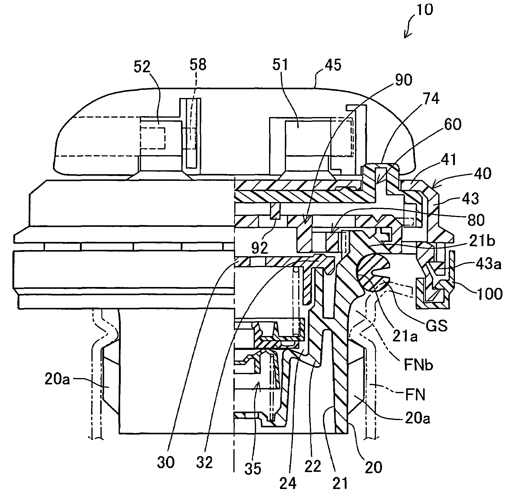
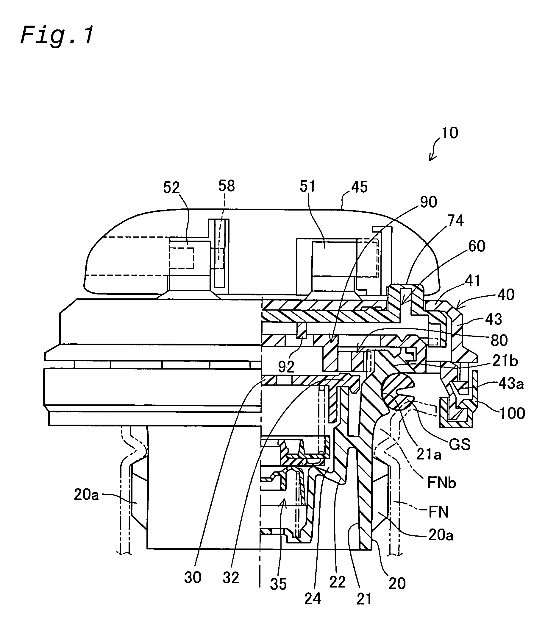
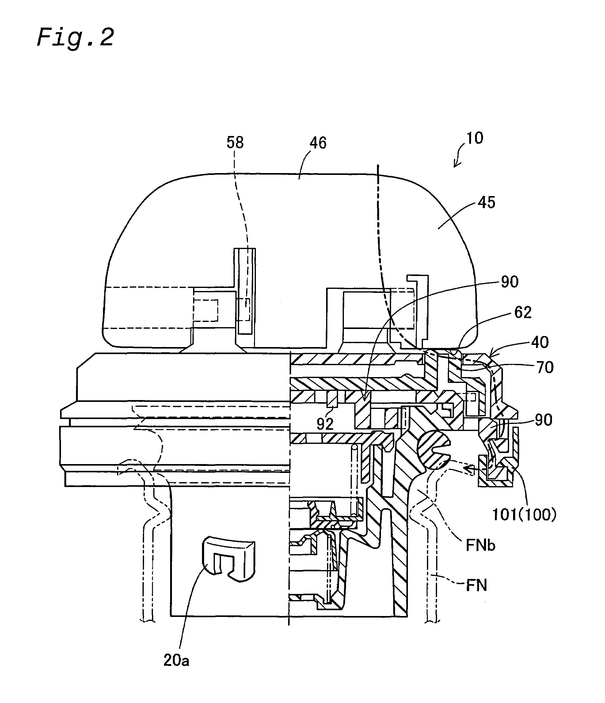
[0056]FIG. 1 is an illustrative diagram showing in partial cutaway a cap device comprising a fuel cap 10 (cap) pertaining to a first embodiment of the invention. In FIG. 1, the fuel cap 10 is attached to a filler neck FN having a filler opening FNb (tank opening) for supplying fuel to a fuel tank, not shown. The cap 10 comprises a casing body 20 (closer) made of polyacetal or other synthetic resin material, an inner cover 30 closing the upper opening of the casing body 20, forming a valve chamber 24; a regulator valve 35 housed within the valve chamber 24; a cover 40 made of nylon or other synthetic resin and mounted on the upper portion of the casing body 20; a handle 45 mounted on the upper face of the cover 40; a clutch mechanism 60 and the torque transmission mechanism 80 (interconnecting mechanism); a tether mechanism 100; and a gasket GS installed on the outside rim of the upper portion of the casing body 20 to provide a seal between t...


PUM


Abstract

A fuel cap has a torque member attached to an upper portion of a casing body. The torque member is a disk-shaped plate to transmit a rotational torque applied to a handle to the casing body. An interlocking recess and interlocking claws, which constitute a plate attachment mechanism, are arranged on the upper portion of the casing member. Fitting of the interlocking claws in the interlocking recess causes the torque member to be attached to the casing body in a freely rotatable manner. This simple structure of the invention effectively prevents the fuel cap from being easily damaged by an inadvertent operation, such as a careless drop of the fuel cap, and ensures the sufficient sealing properties of the fuel cap even under application of an external load.

Description

[0001]This application claims the benefit of and priority from Japanese Applications No. 2002-212785 filed Jul. 22, 2002 and No. 2002-281576 filed Sep. 26, 2002, the contents of which are incorporated herein by reference.BACKGROUND OF THE INVENTION[0002]1. Field of the Invention[0003]The present invention relates to a cap device that is detachably attached to a tank opening member.[0004]2. Description of the Related Art[0005]One known example of the cap device is disclosed in JP No. 10-329861A. FIG. 38 is a partly broken view illustrating a prior art fuel cap 200 for a vehicle. The fuel cap 200 includes a casing body 202, and a cover 210 attached to an upper flange 204 of the casing body 202. The flange 204 has an outer ring element 206 for fixation of the cover 210 and a linkage element 208 for linkage with the casing body 202. The linkage element 208 has a fragile portion including a notch 209. The fragile portion makes a starting point of breaking the linkage element 208 when a l...

Claims


Application Information

Patent Timeline
Patent Type & Authority Patents(United States)
IPC IPC(8): B65D53/00B60K15/04
CPCB60K15/0406Y10S220/33B60K2015/03401
Inventor HAGANO, HIROYUKINAKAGAWA, MASAYUKI
Owner TOYODA GOSEI CO LTD
Why Eureka
Try Eureka