Coded pattern for an optical device and a prepared surface

a technology of optical devices and coded patterns, applied in the field of optical devices, can solve the problems of difficult repeated handling of original documents and electronic forms, difficulty in converting handwritten documents into electronic documents, and difficulty in converting scanned images, etc., and achieves the effect of convenient implementation

Inactive Publication Date: 2006-05-23
MICROSOFT TECH LICENSING LLC
View PDF44 Cites 34 Cited by
  • Summary
  • Abstract
  • Description
  • Claims
  • Application Information

AI Technical Summary

Benefits of technology

[0006]Embodiments of the invention overcome one or more deficiencies in the prior art by providing, among other things, a system and method for encoding and decoding a pattern of symbols on a surface such as a paper or computer display. The pattern of symbols may represent encoded data such as position data, multimedia (e.g., audio, video, image, etc.), security application, biometrics, identify management, other bulk data, or a link to other data. In one embodiment, the invention uniquely identifies positions relating to the surface. According to one or more embodiments of the invention, an optical device such as a digital pen or stylus advantageously tracks its absolute position on a prepared surface by detecting symbols corresponding to position data encoded on the surface. In one or more other embodiments of the invention, the surface is encoded with symbols indicative of the position data by means of a pattern embedded by a printing process, such as a laser printer or an inkjet printer. A sensor of the optical device may then detect the symbols and decode the data that the pattern of symbols represents. Moreover, the features of embodiments of the present invention described herein are economically feasible, commercially practical, and easier to implement than currently available techniques.

Problems solved by technology

One of the difficulties, however, with composing a hand-written document is the need to have the hand-written document converted into an electronic form.
These multiple steps make the interaction between the original document and the electronic form of the document difficult to handle on a repeated basis.
Further, the scanned-in image is frequently non-modifiable.
This makes it difficult for users to alter the information in the electronic form.
Similar difficulties also exist in creating an annotation on a preexisting document.
Since the scanned-in image is frequently non-modifiable, it is difficult to separate the annotation from the original information of the preexisting document.
Some existing patterns, however, do not have efficient ink usage.
That is, the existing methods and systems often require a significant amount of ink or other means to embed a pattern on a surface.
Further, some existing methods and systems do not provide a pattern that is visually smooth enough to effectively prevent users from being distracted by such a pattern when performing a function on a surface encoded with the pattern (e.g., writing on the surface).
Also, the existing methods and systems fail to provide a pattern that has variable information density.
Thus, the existing methods and systems typically do not allow scaling of ink density according to data desired to be encoded.
Additionally, some of the existing patterns are not easy to produce, to decode, and / or to effectively encode a variety of payload data.

Method used


Image

  • Coded pattern for an optical device and a prepared surface
  • Coded pattern for an optical device and a prepared surface
  • Coded pattern for an optical device and a prepared surface

Examples


Embodiment Construction

Exemplary Optical Device

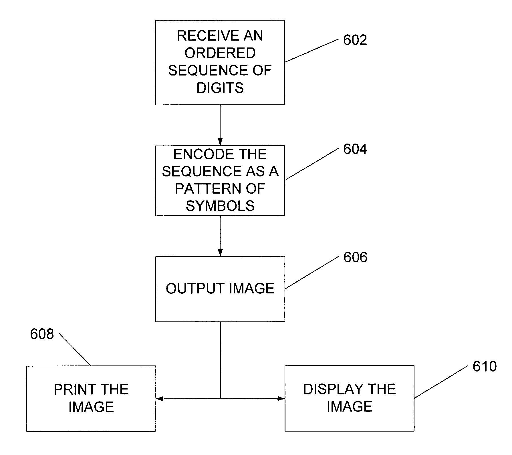
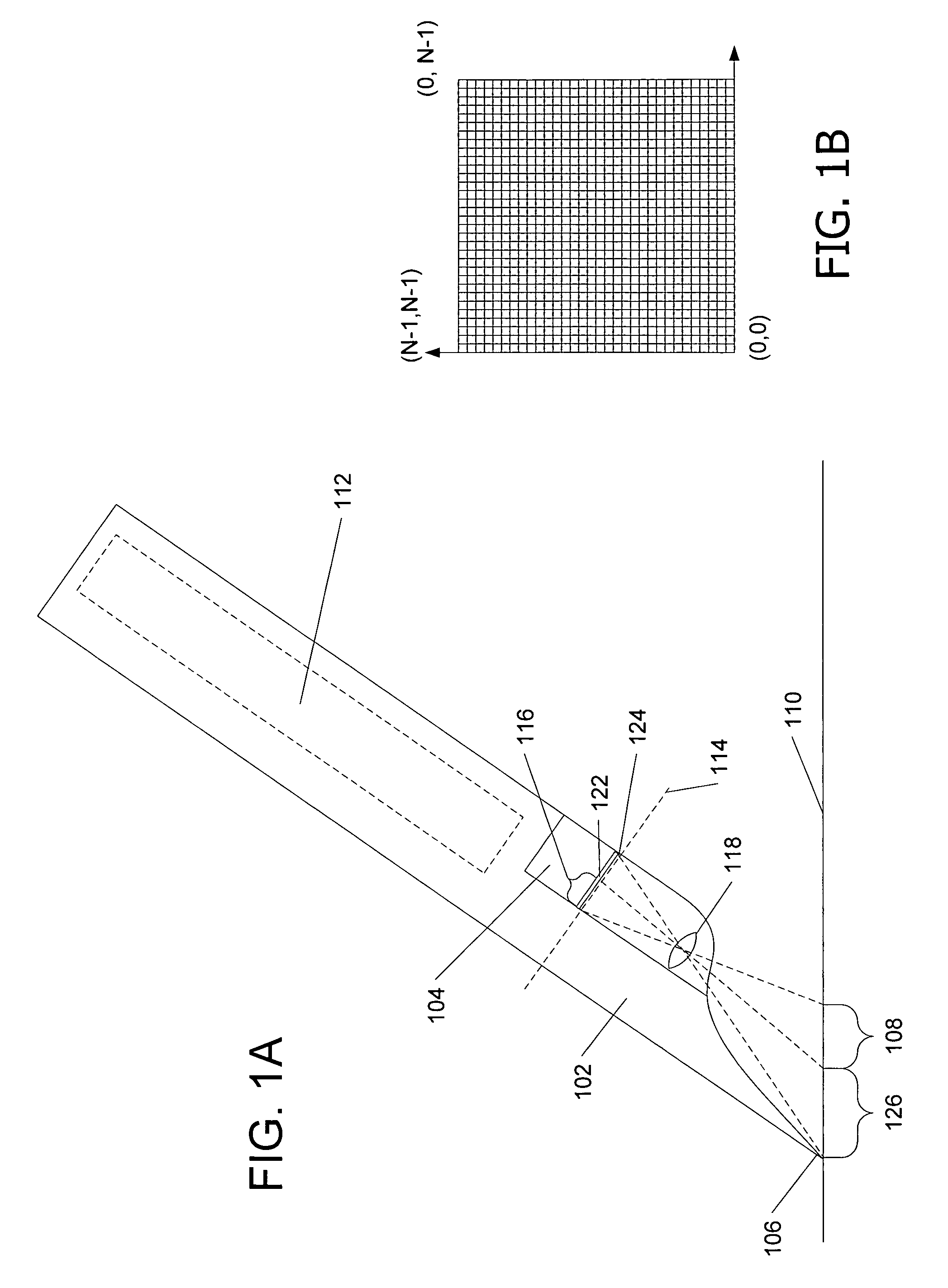
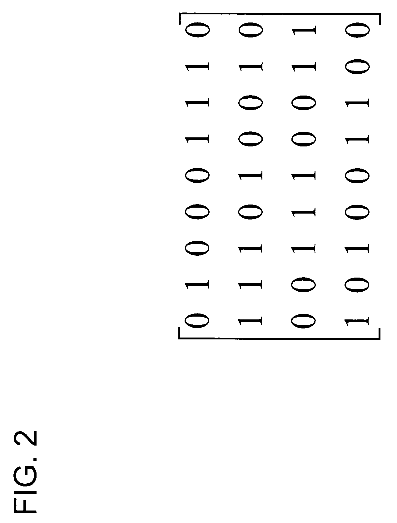
[0024]Embodiments of the present invention relate to an optical device (e.g., an optical imaging sensor or an optical reading device) interacting with a surface to determine encoded information on the surface. In one embodiment of the invention, the optical device may be implemented as a multi-function pen or stylus. Aspects of the present invention also include placing a pattern of symbols in a display form. The pattern of symbols may represent encoded data such as position data, multimedia (e.g., audio, video, image, etc.), security application, biometrics, identify management, other bulk data, or a link to other data. In one embodiment, the display form is a printed paper (or other physical medium) or a display projecting or containing the encoded pattern of symbols in conjunction with another image or set of images. For example, the encoded pattern of symbols may be represented as a physical image on the paper, an image overlying or underlying another dis...


PUM


Abstract

Encoding data in a pattern of symbols on a surface. A processor separates an ordered sequence of digits representative of the encoded data into a plurality of sequential windows. Each of the sequential windows includes a partial sequence of the ordered sequence of digits. The processor further transforms the partial sequence included in each sequential window into a series of digits. A symbol is arranged within a plurality of surface windows on the surface. Each surface window corresponds to one of the sequential windows. The symbol is positioned within each surface window based on one of the transformed series of digits. And the position of the symbol within the surface window is indicative of the encoded data.

Description

TECHNICAL FIELD[0001]Embodiments of the present invention relate to an optical device interacting with a surface to determine encoded information on the surface. In particular, embodiments of this invention relate to such a surface having a pattern, which includes symbols that are based on an ordered sequence of digits divided into windows and that indicate encoded information.BACKGROUND OF THE INVENTION[0002]Computer users are accustomed to using a mouse or keyboard as a way of interacting with a personal computer. While inputting information via a mouse or keyboard provides a number of advantages, most users continue to perform certain functions by composing a hand-written document (e.g., on paper or on a whiteboard). Some advantages of a hand-written document over an electronic document include its readability and portability. Others include the ease at which one can archive a hand-written document. One of the difficulties, however, with composing a hand-written document is the n...

Claims


Application Information

Patent Timeline
Patent Type & Authority Patents(United States)
IPC IPC(8): G06K19/06G06K7/10G06K7/14G06F3/041G06F3/03G06F3/042G06K9/20
CPCG06F3/03545G06F3/0317G06F3/0321
Inventor LADAS, COREYLARSEN, GLEN
Owner MICROSOFT TECH LICENSING LLC
Why Eureka
Try Eureka