Valve with removable actuator

Inactive Publication Date: 2006-05-23
CALEFFI
View PDF41 Cites 62 Cited by
  • Summary
  • Abstract
  • Description
  • Claims
  • Application Information

AI Technical Summary

Benefits of technology

[0004]The actuator assembly may be either permanently secured to the valve body or releasably engaged with the valve body. Permanent mounting of the actuator to the valve body is disadvantageous in that the entire valve assembly including the valve body must be removed when the actuator assembly requires service or replacement. Releasable engagement of the valve actuator assembly with the valve body has the advantage of enabling the actuator assembly to be freely removed and replaced independent of the valve body, such that the valve body remains in place when the actuator is remover for repair or replacement.
[0005]It is an object of the present invention to provide a valve actuator having a number of advantages in construction, operation and assembly over prior art valve actuators. It is a further object of the invention to provide a valve actuator which can be easi

Problems solved by technology

Permanent mounting of the actuator to the valve body is disadvantageous in that the entire valve assemb

Method used


Image

  • Valve with removable actuator
  • Valve with removable actuator
  • Valve with removable actuator

Examples


Embodiment Construction

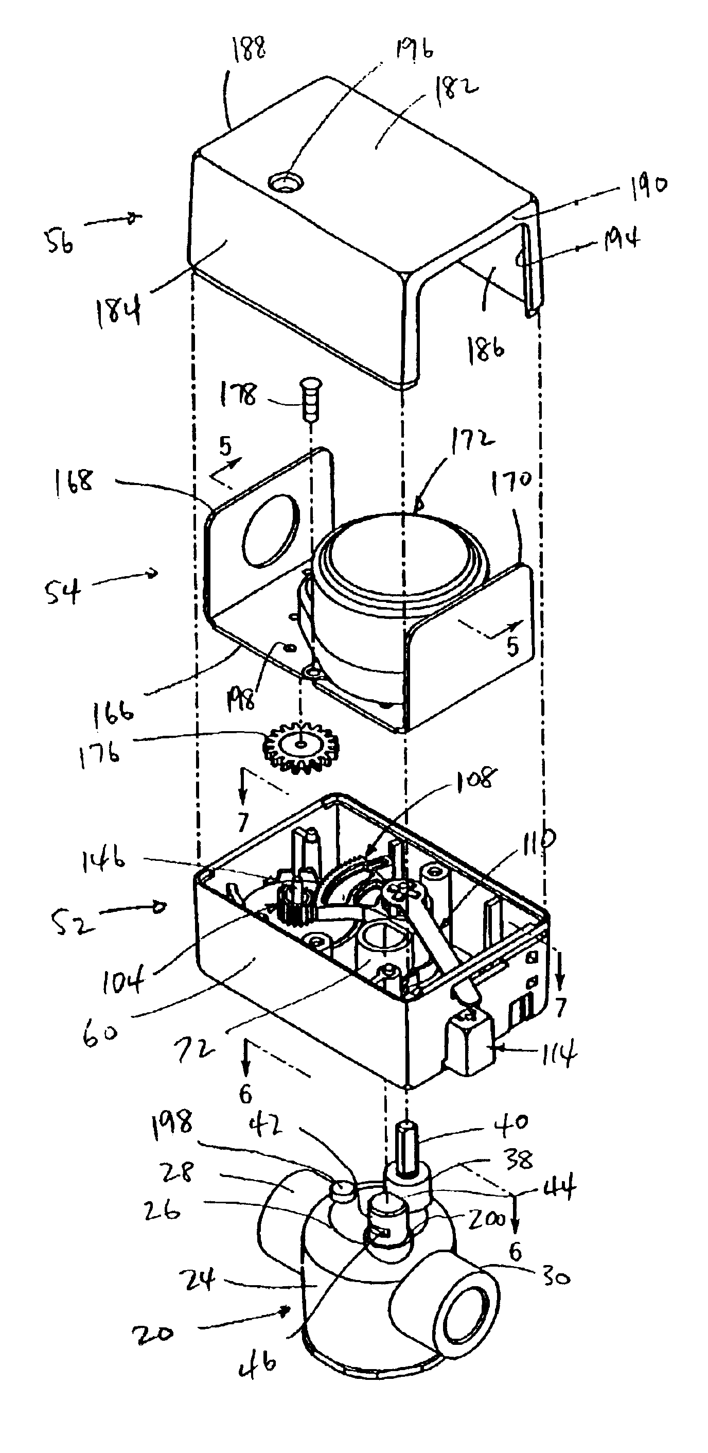
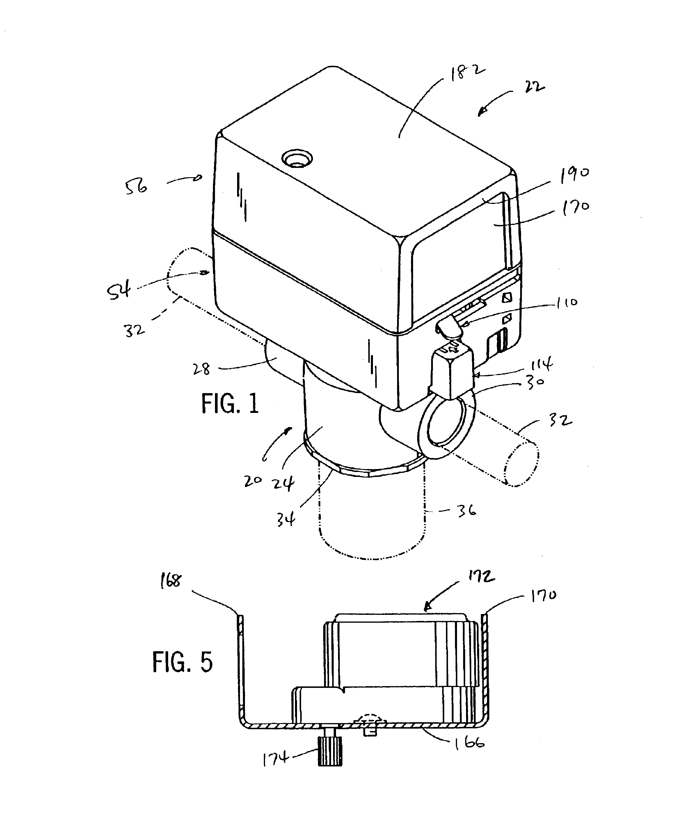
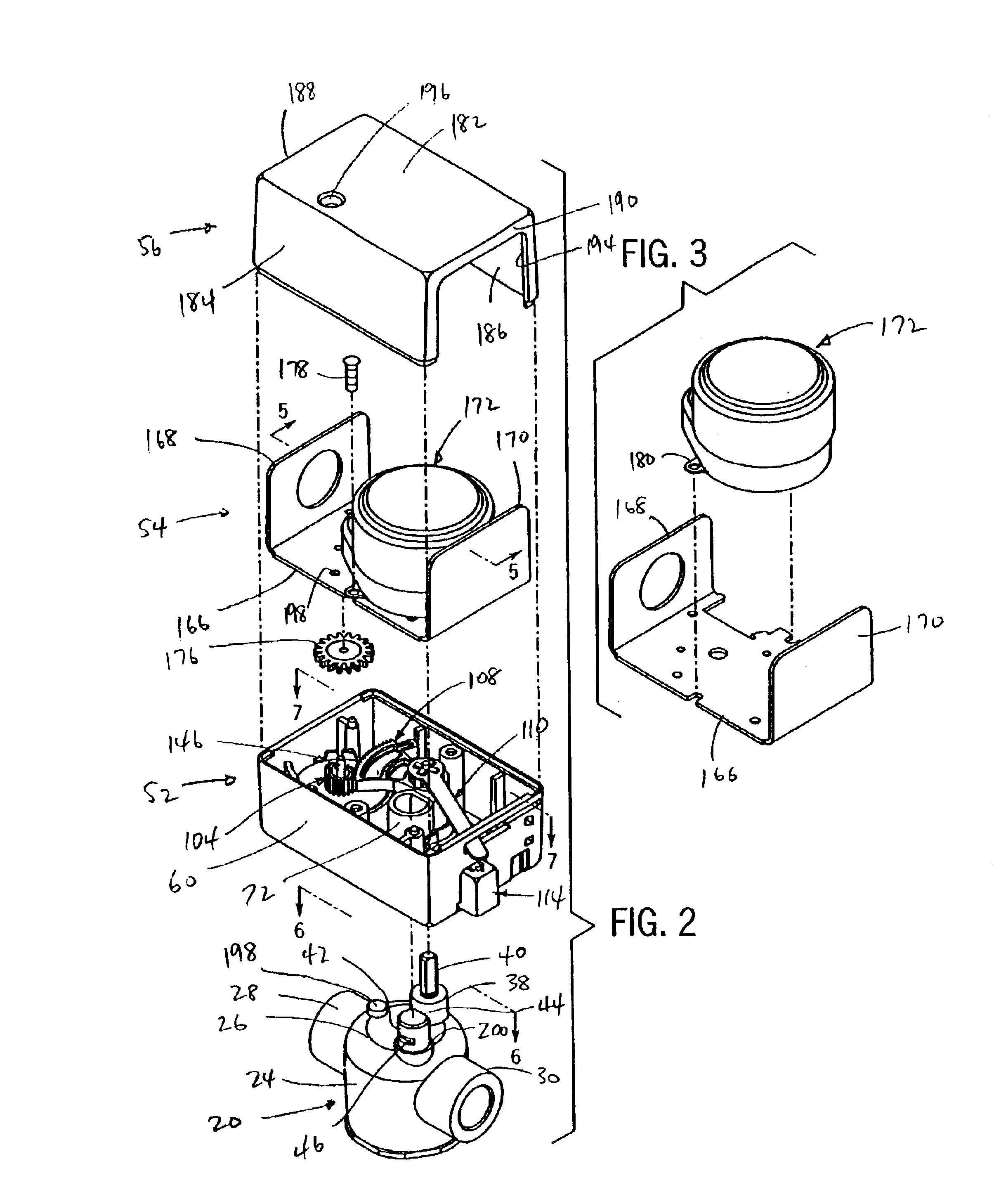
[0025]Referring to FIGS. 1 and 2, a valve assembly in accordance with the present invention includes a valve body 20 and a valve actuator 22. Valve body 20 includes a peripheral side wall 24 and a domed end wall 26. A pair of nipples 28, 30 are adapted to be plumbed into a fluid flow line, such as shown at 32, which may representatively be a line used in a water-operated heating system or in any other application requiring regulation of fluid flow in a line. In a manner as is known, each nipple defines a passage that communicates with the interior of valve body 20, which defines an internal cavity within which a conventional valve member is received. In a known manner, the valve member is movable between an open position to allow fluid flow in line 32, and a closed position to cut off fluid flow. In the closed position, the valve member is seated against an inside seating surface located in the internal cavity of valve body 20.

[0026]In a two-way valve application, an end cap 34 is e...


PUM


Abstract

A valve assembly includes a valve body and a valve actuator which is releasably engageable with the valve body. The valve body has an internal cavity within which a valve member is located, and a valve stem is interconnected with the valve body and is accessible from the exterior of the valve body. The valve body further includes a mounting member, and the valve actuator is selectively engageable with the mounting member. The valve actuator includes a latch member which is movable between a latching position and a release position. The mounting member includes a slot, and the latch member has a blocking member that is received within the slot when the latch member is in its latching position, to prevent removal of the valve actuator from the valve body. The latch member is manually movable to a release position, in which the blocking member is removed from the slot in the mounting member to enable the valve actuator to be disengaged from the mounting member. The valve actuator includes a motor which drives a gear assembly for selectively imparting rotation to the valve member. The motor is secured to a mounting member such as a mounting plate. The mounting plate includes one or more walls that are exposed to the exterior of the valve actuator, such that heat from operation of the motor is conducted via the mounting plate away from the motor to the one or more walls for dissipation into the surrounding environment.

Description

BACKGROUND AND SUMMARY OF THE INVENTION[0001]This invention relates to a valve, and more particularly to a valve assembly including a valve body having a movable valve member, and an actuator adapted for engagement with the valve body for providing movement of the valve member within the valve body.[0002]Valves are used in a number of applications to control fluid flow. One type of valve includes a valve body within which a movable valve member is located. The valve body includes an inlet port adapted to communicate with a fluid supply conduit, and an outlet port adapted to communicate with an outlet conduit. Movement of the valve member is operable to open or close the outlet port, to selectively enable fluid flow through the outlet port. In another embodiment, the valve body includes a pair of inlet ports and an outlet port. The valve member is operable to selectively close one of the inlet ports, to enable communication between the outlet port and the open inlet port.[0003]The va...

Claims


Application Information

Patent Timeline
IPC IPC(8): F16K35/02F16K31/05
CPCF16K31/055
Inventor SCHREINER, MICHAEL R.
Owner CALEFFI
Why Eureka
Try Eureka