Vehicle suspension beam

a technology for suspension beams and vehicles, applied in the direction of suspension arms with a pivoting position, suspension systems, resilient suspensions, etc., can solve the problems of metal fatigue, weakening of welded joints, and failure, and achieve the effect of increasing the transverse rigidity of the beam section and strengthening the connection

Inactive Publication Date: 2006-05-23
MERITOR HEAVY VEHICLE SYST
View PDF88 Cites 37 Cited by
  • Summary
  • Abstract
  • Description
  • Claims
  • Application Information

AI Technical Summary

Benefits of technology

[0015]A shear plate or plates are secured across the interior of the beam to increase the transverse rigidity of the beam's section, if required.
[0016]The suspension beam of the present invention has a substantially stronger connection between the beam and axle wrap as a result of the internal and external welded jointing at the side walls of the beam; than has been possible with the known suspension be...

Problems solved by technology

A problem experienced with this known suspension beam is that the welded jointing is wea...

Method used


Image

  • Vehicle suspension beam
  • Vehicle suspension beam

Examples


Embodiment Construction

[0022]The suspension beam of the present invention is provided for a trailing arm suspension of a trailer vehicle.

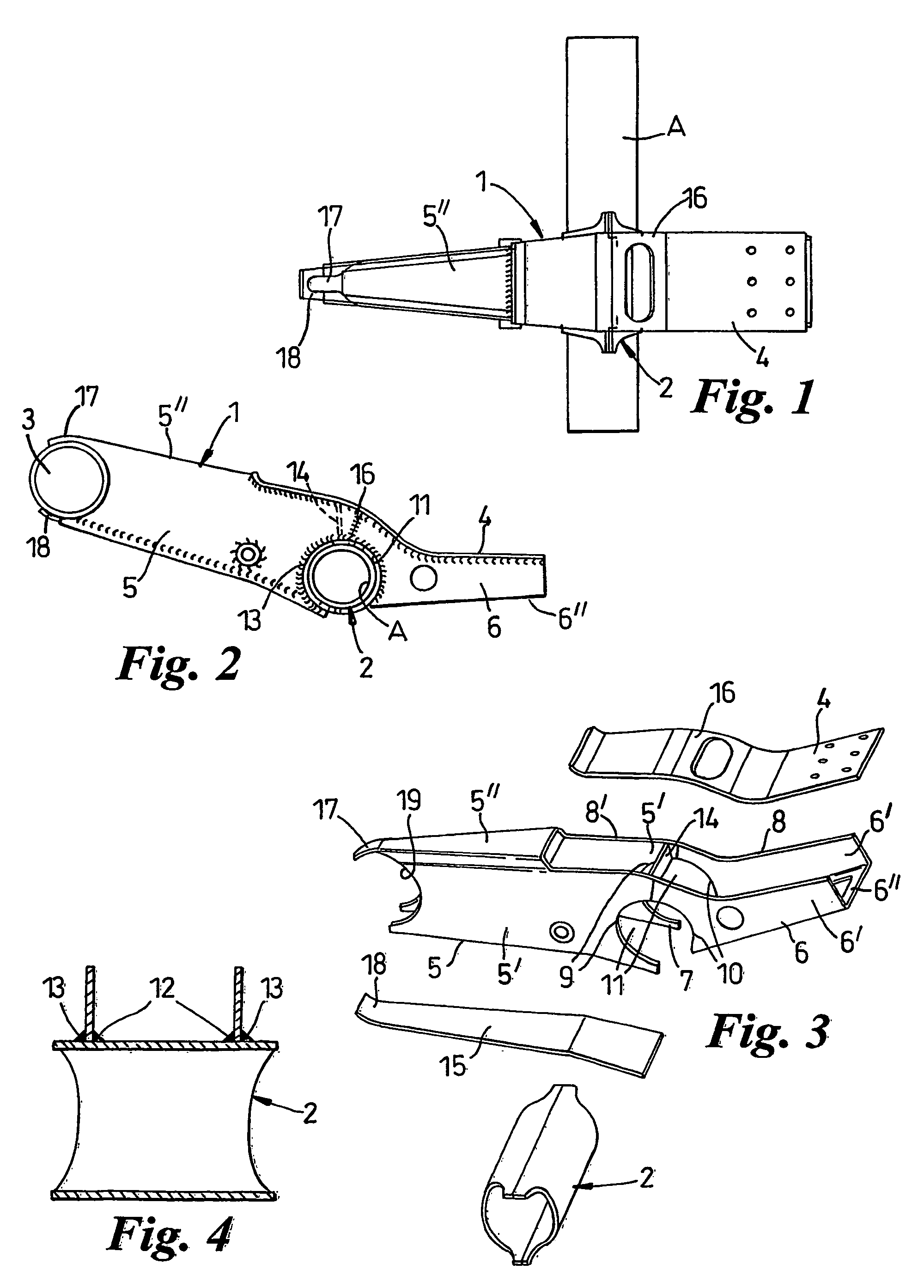
[0023]As shown in FIG. 1. the suspension beam includes a beam proper 1 and an axle wrap 2 secured transversely to the beam 1 at an intermediate part of the length of the beam 1. In use, as shown in FIG. 2, a pivot brush 3 is secured to a front end of the beam 1, an air spring, (not shown,) is mounted on a seating 4 provided on the rearward end part of the beam 1, and the axle wrap 2 is secured on an axle A.

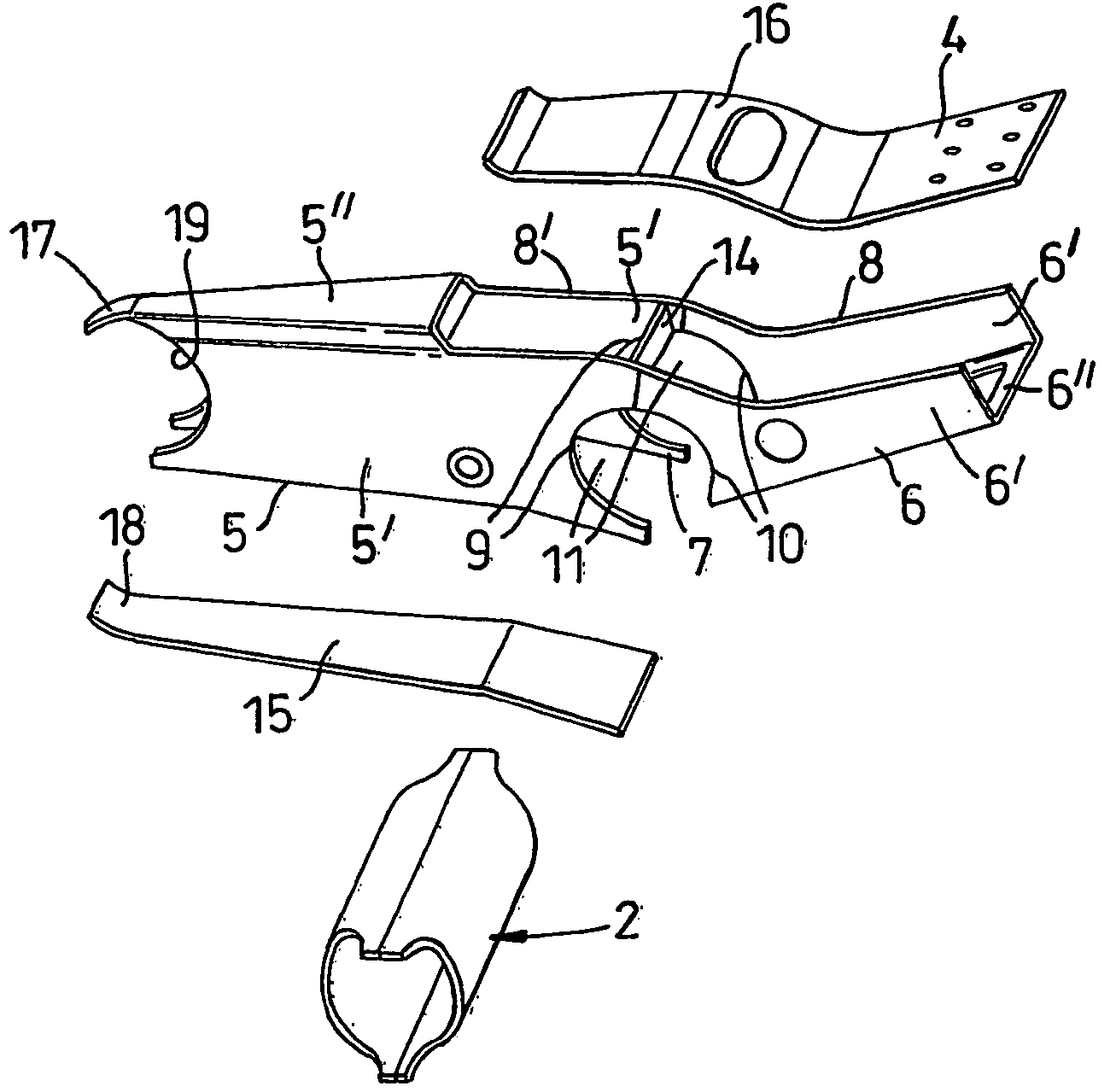
[0024]As best seen in FIG. 3, the beam 1 comprises two elongate, forward and rearward; components 5, 6, respectively, which are each of a generally U-shaped section and are butt-welded end-to-end. Each component 5, 6 is made from metal plate cut to the required outline and formed to the generally U-shaped section. Each of the components 5, 6 include opposed side limbs 5′, 6′, respectively, and a web 5″, 6″, respectively, that are straight and meet at right angles to fo...


PUM


Abstract

A hollow vehicle suspension beam has opposed side walls formed with recesses in which an axle wrap is located and secured by welded jointing. The welded jointing is located internally and externally of the opposed side walls to provide a strong joint between the beam and the axle wrap. The beam includes at least one component of a generally U-shaped section having opposed limbs that provide at least part of the opposed side walls of the beam. The mouth of the component provides an access opening into the interior of the beam for the internal welded jointing to be made at the axle wrap. In one example, the beam includes two U-shaped components disposed with their mouths opening in opposite directions to provide access to the interior of the beam for the internal welded jointing to be made at the axle wrap. The mouths are then closed by closure components. The opposed side walls formed in combination by the opposed limbs of the U-shaped component and the space between the plate components are closed off by closure components after the internal welded joint has been made.

Description

[0001]This application is the National Stage of International Application PCT / GB01 / 03895 filed on Aug. 31, 2001.BACKGROUND OF THE INVENTION[0002]This invention relates generally to a vehicle suspension beam that is pivotal at one end to a support for use, carries a spring means at or towards its opposite end, and has an axle connected to the beam at an intermediate part of its length.[0003]Suspension beams are known which are of a box-section fabricated from metal plate. An axle wrap, that retains an axle is secured transversely of its length in complementary recesses formed in the beam. The axle wrap is secured to the exterior of the beam by welding or adhesive jointing. A problem experienced with this known suspension beam is that the welded jointing is weakened by metal fatigue and can fail when the axle and the beam are subjected to loading in use.SUMMARY OF THE INVENTION[0004]The present invention is aimed at providing a vehicle suspension beam having a stronger joint between a...

Claims


Application Information

Patent Timeline
IPC IPC(8): B60G9/02B60G7/00B60G9/00
CPCB60G9/003B60G21/051B60G7/001B60G2204/148B60G2204/4306B60G2206/11B60G2206/20B60G2206/722B60G2206/8201B60G2204/126B60G2200/21B60G2200/31B60G2202/136B60G2202/152
Inventor CHAN, DAVIDPEAKER, MARTIN
Owner MERITOR HEAVY VEHICLE SYST
Why Eureka
Try Eureka