Golf club shaft

a golf club and shaft technology, applied in the field of golf club shafts, can solve the problems of insufficient flexural flexural force of shafts, large ei of flexural rigidity, etc., and achieve the effect of high trajectory and high strength

Inactive Publication Date: 2006-05-23
DUNLOP SPORTS CO LTD
View PDF6 Cites 17 Cited by
  • Summary
  • Abstract
  • Description
  • Claims
  • Application Information

AI Technical Summary

Benefits of technology

[0012]The present invention has been made in view of the above-described problems. Therefore it is an object of the present invention to provide a golf club shaft having a large diameter at its tip side to allow the tip side to have a high strength and allowing the golf ball to fly in a high trajectory by setting the torsional rigidity and flexural rigidity of the shaft appropriately.
[0014]As described above, the outer diameter of the shaft is set to 9.5 mm to 12 mm larger than that (9.0 mm) of ordinary shafts in at least one portion of the range from the tip of the shaft to the position located at 25% of the distance from the tip to its butt and more favorably in the range from the tip of the shaft to the position located 10% of the distance from the tip to the butt, namely, in the region covering the portion of the shaft inserted into the hose 1 of the neck of the head and the portion of the shaft projected a certain distance from the neck. Thereby the strength of the shaft can be enhanced. Therefore when the shaft is mounted on the head which is thin and has a short neck to lower its center of gravity, the shaft is capable of withstanding an increased load applied to the tip side thereof.
[0016]Merely enlarging the outer diameter of the shaft at its tip side makes the rigidity thereof so high that a ball hit with the shaft flies in a low trajectory. Thus in the range of the shaft in which the outer diameter is set larger, the minimum value of the flexural rigidity (EI) of the golf club shaft is set to 1.00 to 2.50 kg·m2 to allow the flexural rigidity (EI) to be proper. Therefore the shaft is allowed to be flexible without deteriorating the strength at its tip side. Thus the golf ball has a large elevation angle when it is hit and flies in a high trajectory.

Problems solved by technology

On the other hand, if the outer diameter of the shaft at its tip side is more than 12.0 mm, the value of the flexural rigidity (EI) becomes so large that it is impossible to make the shaft sufficiently flexural.

Method used


Image

  • Golf club shaft
  • Golf club shaft
  • Golf club shaft

Examples


example 1

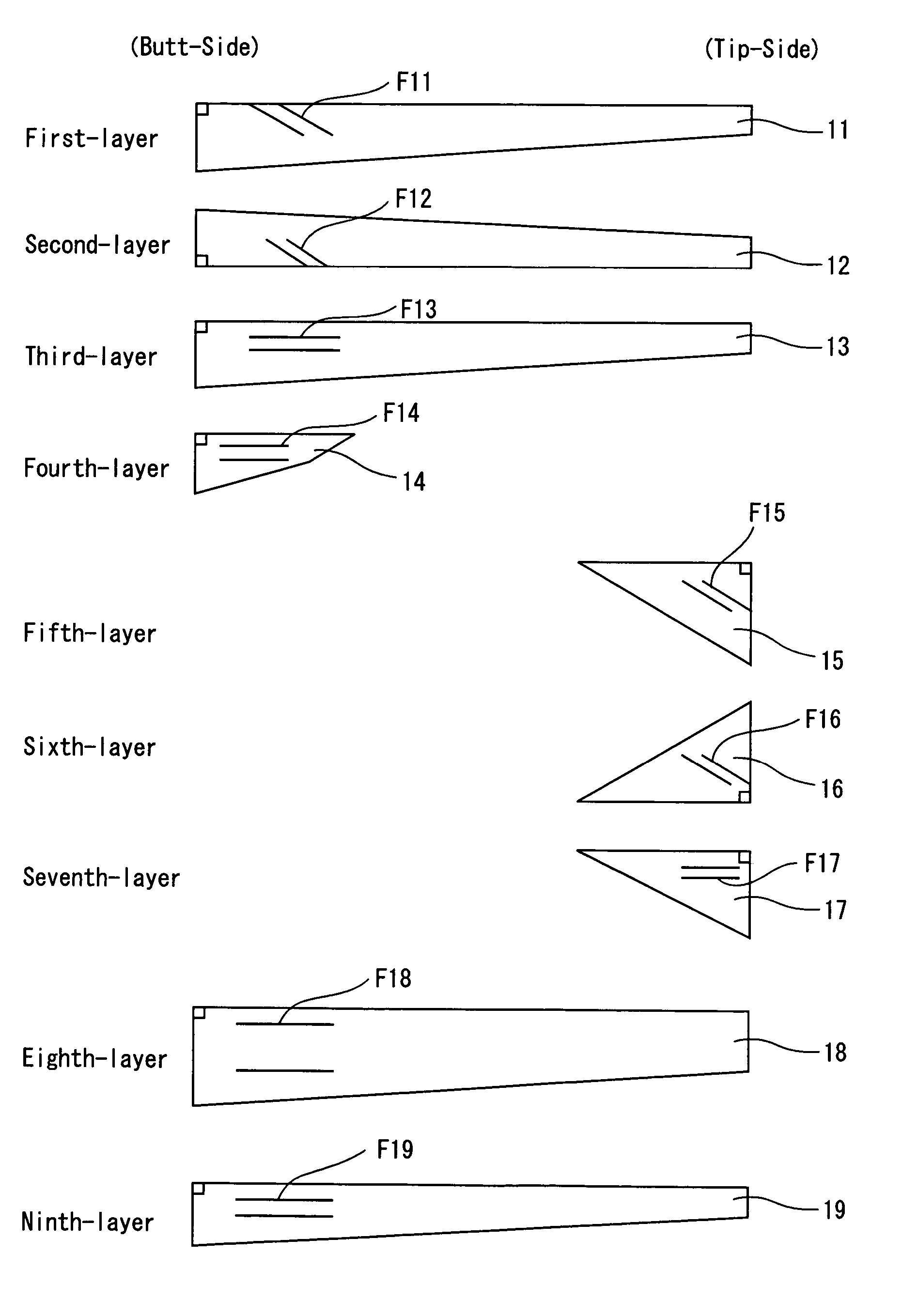
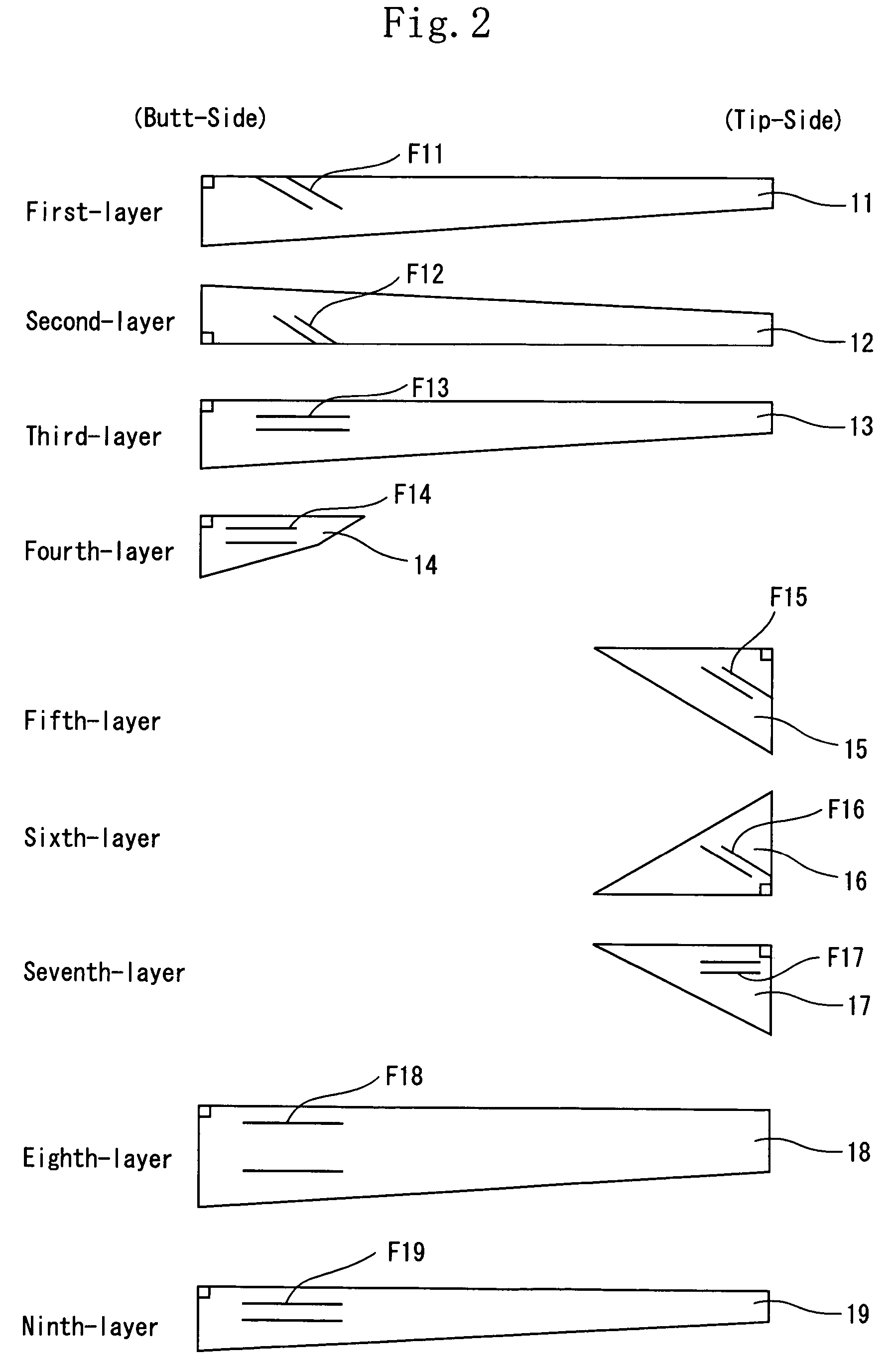
[0061]The shaft of the example 1 was similar to that of the first embodiment in its construction. More specifically, the tip-side reinforcing layer was formed in the range from the tip of the shaft to the position located at 20% of the distance from the tip to the butt. The fifth-layer and sixth-layer prepregs were formed as the tip-side reinforcing angular layers. The reinforcing fiber of the fifth-layer prepreg and that of the sixth-layer prepreg had an orientation angle of −45 and +45° respectively. The reinforcing fiber of each of the fifth-layer prepreg and the sixth-layer prepreg had a tensile modulus of elasticity of 24 ton / mm2. The seventh-layer prepreg was formed as the tip-side reinforcing straight layer. The reinforcing fiber of the seventh-layer prepreg had a tensile modulus of elasticity of 10 ton / mm2. The ratio of the weight of the tip-side reinforcing straight layer to that of the tip-side reinforcing angular layer was set to 0.7. The diameter of the tip of the shaft ...

example 2

[0063]The tip-side reinforcing layer was formed in the range from the tip of the shaft to the position located at 25% of the distance from the tip to the butt. The fifth-layer and sixth-layer prepregs were formed as the tip-side reinforcing angular layers. The reinforcing fiber of the fifth-layer prepreg and that of the sixth-layer prepreg had an orientation angle of −60° and +60° respectively. The reinforcing fiber of each of the fifth-layer prepreg and the sixth-layer prepreg had a tensile modulus of elasticity of 30 ton / mm2. The seventh-layer prepreg was formed as the tip-side reinforcing straight layer. The reinforcing fiber of the seventh-layer prepreg had a tensile modulus of elasticity of 15 ton / mm2. The ratio of the weight of the tip-side reinforcing straight layer to that of the tip-side reinforcing angular layer was set to 0.75. The diameter of the tip of the shaft was set to 9.5 mm. The length of the shaft was set to 991 mm. The minimum value of the flexural rigidity (EI)...

example 3

[0065]The tip-side reinforcing layer was formed in the range from the tip of the shaft to the position located 15% of the distance from the tip to the butt. The fifth-layer and sixth-layer prepregs were formed as the tip-side reinforcing angular layers. The reinforcing fiber of the fifth-layer prepreg and that of the sixth-layer prepreg had an orientation angle of −20° and +20° respectively. The reinforcing fiber of each of the fifth-layer prepreg and the sixth-layer prepreg had a tensile modulus of elasticity of 30 ton / mm2. The seventh-layer prepreg was formed as the tip-side reinforcing straight layer. The reinforcing fiber of the seventh-layer prepreg had a tensile modulus of elasticity of 5 ton / mm2. The ratio of the weight of the tip-side reinforcing straight layer to that of the tip-side reinforcing angular layer was set to 0.80. The diameter of the tip of the shaft was set to 10.0 mm. The length of the shaft was set to 991 mm. The minimum value of the flexural rigidity (EI) in...


PUM


Abstract

A golf club shaft whose outer diameter is set to 9.5 to 12 mm in at least one portion of a range from a tip thereof to a position located at 25% of the distance from the tip to its butt. The minimum value of a flexural rigidity (EI) is set to 1.00 to 2.50 kg·m2. A reinforcing layer is formed in the region disposed from the tip to the position located at about 25% of the distance from the tip to the butt. The layer includes at least one straight layer whose reinforcing fiber has a tensile modulus of elasticity of 5 to 15 ton / mm2 and is parallel with an axis of the shaft and one angular layer whose reinforcing fiber has a tensile modulus of elasticity of 24 to 40 ton / mm2 and an orientation angle of ±20 to 65°.

Description

[0001]This Nonprovisional application claims priority under 35 U.S.C. § 119(a) on patent application No(s). 2002-336783 filed in JAPAN on Nov. 20, 2002, the entire contents of which are hereby incorporated by reference.BACKGROUND OF THE INVENTION[0002]1. Field of the Invention[0003]The present invention relates to a golf club shaft and more particularly to a golf club shaft in which the center of gravity of the head is lowered in such a way as to maintain the strength of the shaft at its tip side on which a head is mounted and which is flexible to fly a golf ball at a large elevation angle.[0004]2. Description of the Related Art[0005]In recent years, a golf club shaft composed of a reinforcing fiber such as a carbon fiber having a high specific strength and a high specific rigidity is manufactured and commercially available. As the specific strength and the specific rigidity of the carbon fiber become higher, a lightweight golf club shaft can be manufactured.[0006]To allow the golf ...

Claims


Application Information

Patent Timeline
Patent Type & Authority Patents(United States)
IPC IPC(8): A63B53/10A63B102/32
CPCA63B53/10A63B59/0014A63B2209/023A63B2059/0081A63B2209/02A63B59/0092A63B60/06A63B60/08A63B60/10A63B60/54A63B60/0081
Inventor KUMAMOTO, TOMIO
Owner DUNLOP SPORTS CO LTD
Why Eureka
Try Eureka