Radio frequency power measurement

a radio frequency and power measurement technology, applied in the direction of frequency analysis, frequency measurement arrangement, direction finders, etc., can solve problems such as significant errors

Inactive Publication Date: 2006-05-23
RACAL INSTR WIRELESS SOLUTIONS
View PDF16 Cites 4 Cited by
  • Summary
  • Abstract
  • Description
  • Claims
  • Application Information

AI Technical Summary

Benefits of technology

[0011]It is an object of the present invention to provide a RF power measurement system which at least alleviates the foregoing problem.
[0012]According to the present invention the variability in RF power reading with temperature is significantly reduced by providing a second detector driven by a constant RF power source. In effect, variations in the characteristic of the first detector with temperature can be compensated for by observing variations in the characteristic of the second detector.

Problems solved by technology

If a measurement of an unknown RF power is made at a different temperature from the temperature at the time of calibration, significant errors result.

Method used


Image

  • Radio frequency power measurement
  • Radio frequency power measurement
  • Radio frequency power measurement

Examples


Embodiment Construction

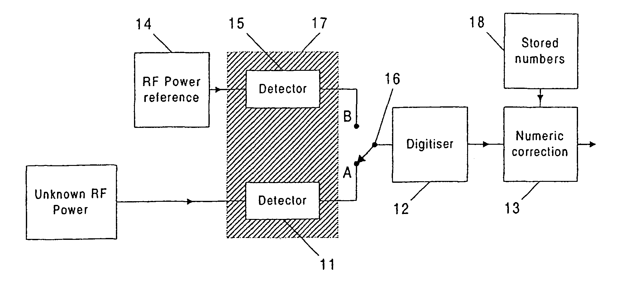
[0020]Referring to FIG. 3, the unknown RF power to be measured is supplied to a first detector 11. With a switch 16 in position A, a digitiser 12 gives a numeric output N11meas corresponding to the voltage output from the detector 11, which is then scaled in a numeric correction block 13 to give the result. This part of the system is similar to the known RF power measurement system shown in FIG. 1.

[0021]Referring again to FIG. 3, a RF power reference 14 is an oscillator with a well-defined output level and low harmonic content. This may be provided, for example, by an oscillator followed by a divider circuit to give a 50% duty cycle, which in turn switches a well defined current on and off into a fixed load resistor. Harmonics from the resulting squarewave output can be removed by a bandpass filter centred on the output frequency of the oscillator. With suitable selection of components and choice of operating frequency, the output level can be made almost independent of temperature....


PUM


Abstract

An unknown RF power is converted to a voltage by a detector (11). The voltage is converted to a number by a digitiser (12). A separate and fixed RF power reference (14) drives a second detector (15), whose voltage output is also converted to a number by the digitiser (12). The RF detectors are thermally coupled. Temperature variations in the RF power to voltage characteristic of the detector (11) are corrected by measuring the RF power reference (14) via the detector (15).

Description

FIELD OF THE INVENTION[0001]This invention relates to the measurement of radio frequency (RF) power.BACKGROUND[0002]FIG. 1 of the accompanying drawings is a block diagram showing a known technique for measuring RF power.[0003]The unknown RF power to be measured is applied to a detector 1, which converts the RF power into a more easily measurable quantity, such as voltage or temperature (which may in turn be converted to voltage). The voltage representing the RF power is digitised by a digitiser 2. To provide a reading of RF power to the user of the equipment, the output of the digitiser is usually scaled by a numeric correction function in numeric correction block 3, which takes into account the transfer function of the detector, and any fixed offsets which would otherwise give errors at low RF powers.[0004]In a practical implementation of the technique described, the detector block is typically a diode followed by a capacitor. The transfer function of this block, expressed as volta...

Claims


Application Information

Patent Timeline
Patent Type & Authority Patents(United States)
IPC IPC(8): G01R23/00G01R19/00G01R21/10G01R21/01G01R21/133G01R21/14G01R22/04
CPCG01R22/04G01R21/133G01R21/14
Inventor ROSE, IAN MICHAELWEBB, NIGEL KENNETHWARD, CHRISTOPHER JOHN
Owner RACAL INSTR WIRELESS SOLUTIONS
Why Eureka
Try Eureka