Moisture sensor with capacitive moisture measuring element and method of determining air humidity

a moisture sensor and capacitive technology, applied in the direction of instruments, material analysis, measurement devices, etc., can solve the problem of rising to unacceptably large deviations between air humidity values, and achieve the effect of improving the level of measuring accuracy

Active Publication Date: 2006-05-23
SIEMENS SWITZERLAND
View PDF12 Cites 8 Cited by
  • Summary
  • Abstract
  • Description
  • Claims
  • Application Information

AI Technical Summary

Benefits of technology

[0009]The object of the present invention is to improve known methods of determining air humidity in such a way that it is possible to achieve a substantial improvement in the level of measuring accuracy with a conventional capacitive moisture measuring element. In this respect the invention also seeks to provide an apparatus with which the method can be carried into effect.

Problems solved by technology

Experience has shown that this simplification, for certain uses, gives rise to unacceptably large deviations between an air humidity value ascertained in the known manner and the air humidity value which is actually present.

Method used


Image

  • Moisture sensor with capacitive moisture measuring element and method of determining air humidity
  • Moisture sensor with capacitive moisture measuring element and method of determining air humidity
  • Moisture sensor with capacitive moisture measuring element and method of determining air humidity

Examples


Embodiment Construction

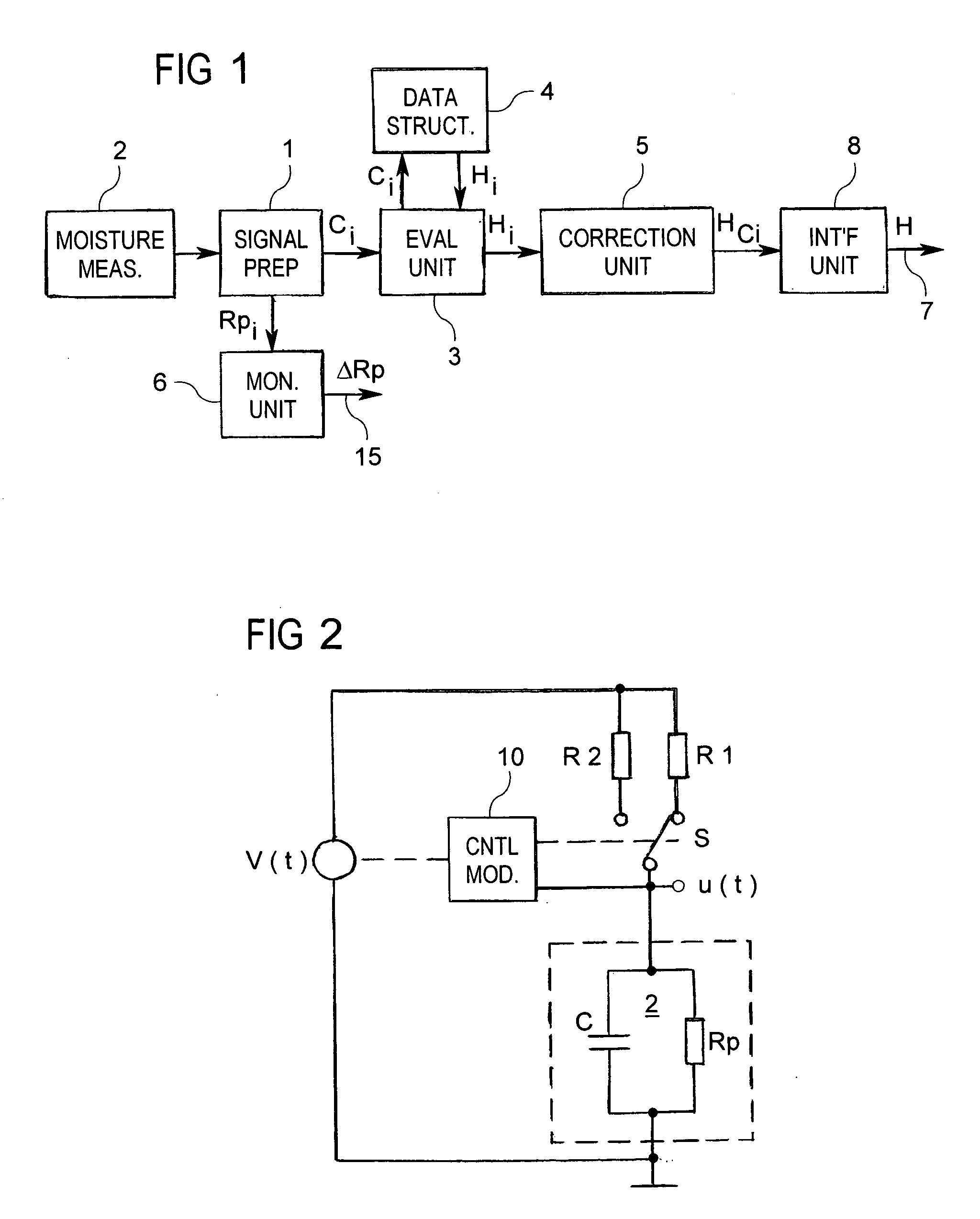
[0022]A moisture sensor shown in FIG. 1 has a capacitive moisture measuring element 2 connected to a signal preparation unit 1 and an evaluation unit 3 connected on the output side of the signal preparation unit 1.

[0023]In an advantageous implementation the moisture sensor also has a data structure 4 which can be used for the evaluation unit 3. For further improving the properties involved the moisture sensor can be supplemented by a correction unit 5 connected on the output side of the evaluation unit 3 and / or a monitoring unit 6 connected to the signal preparation unit 1. A moisture signal H at an output 7 of the moisture sensor can advantageously be matched by way of an interface unit 8.

[0024]Depending on the respective requirements involved the moisture signal H in the interface unit is prepared for a standard provided at the output 7, for example in the form of a digital signal and / or in the form of an analog signal.

[0025]Certain electrical properties such as a capacitance or a...


PUM

PropertyMeasurementUnit
frequencyaaaaaaaaaa
voltage thresholdaaaaaaaaaa

Abstract

In a method of determining air humidity, a corrected moisture signal is calculated for a moisture signal (Hi) ascertained from electrical properties of a capacitive moisture measuring element. In a measuring phase (30) with rising relative air humidity (RH), the corrected moisture signal is the current moisture signal (Hi) increased by a correction value, whereas in a measuring phase (31) with falling relative air humidity (RH) the corrected moisture signal is the current moisture signal (Hi) reduced by a correction value. Depending on the respective properties of the moisture measuring element and the required degree of measuring accuracy, the correction value is constant or is taken into consideration in dependence on the relative air humidity RH. This method provides a higher level of measuring accuracy with a moisture sensor equipped with the moisture measuring element.

Description

BACKGROUND OF THE INVENTION[0001]1. Field of the Invention[0002]The invention relates to a method of determining moisture with a capacitive moisture-sensitive element, and an apparatus for carrying out the method.[0003]2. Description of Prior Art[0004]Such apparatuses and methods are advantageously used in the heating, ventilation and air-conditioning art (HVAC) for buildings for determining the air humidity in a room or in a device for supplying or discharging air.[0005]Capacitive moisture measuring elements deliver a capacitance value in dependence on the air humidity in the area around the measuring element. That capacitance value can be measured by means of an electronic evaluation system. A current moisture value is ascertained with the measured capacitance value, using further parameters such as temperature and comparative parameters.[0006]Capacitive moisture measuring elements are available on the market in various different forms, and by way of example reference will be made...

Claims


Application Information

Patent Timeline
Patent Type & Authority Patents(United States)
IPC IPC(8): G01R27/26G01N27/22
CPCG01N27/225
Inventor LUTHI, YVES
Owner SIEMENS SWITZERLAND
Why Eureka
Try Eureka