Miniature highly manufacturable mouse pointing device

Active Publication Date: 2006-05-23
INTERLINK ELECTRONICS
View PDF53 Cites 13 Cited by
  • Summary
  • Abstract
  • Description
  • Claims
  • Application Information

AI Technical Summary

Benefits of technology

[0011]The present invention decreases the cost and complexity of an electronic mouse pointing device by constructing the device in a manner permitting assembly into user interfaces with industry standard high v

Problems solved by technology

Moving the stick creates strain induced changes in resistance.
One difficulty with such devices is that the strain induced resistance change creates a small signal, requiring amplification and introducing noise susceptibility.
In addition, these devices have a flex circuit tail wh

Method used


Image

  • Miniature highly manufacturable mouse pointing device
  • Miniature highly manufacturable mouse pointing device
  • Miniature highly manufacturable mouse pointing device

Examples


Embodiment Construction

)

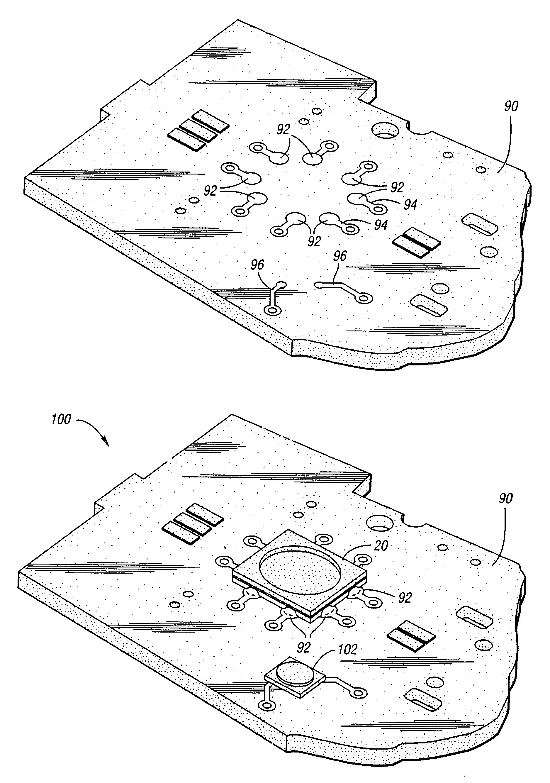
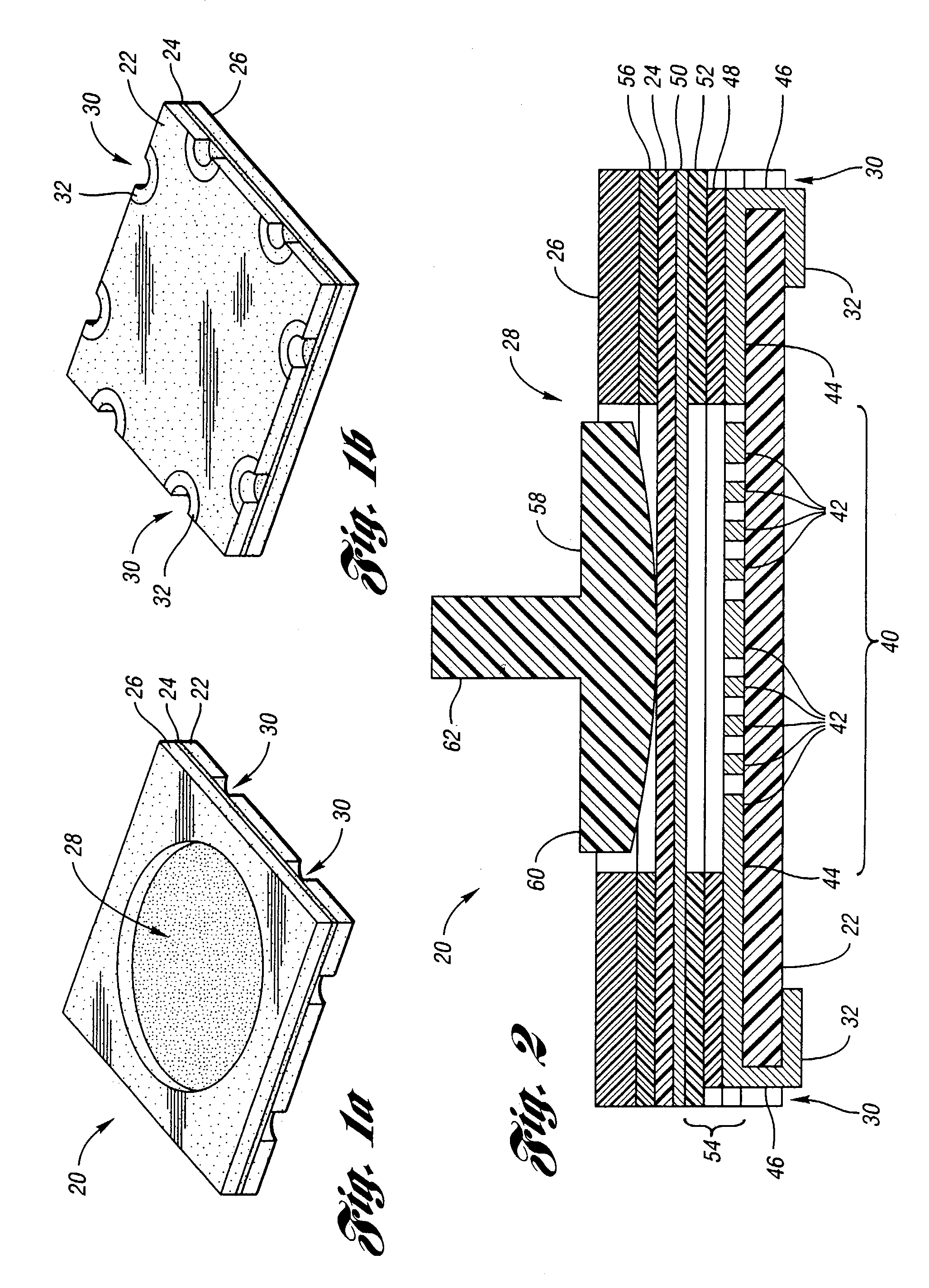
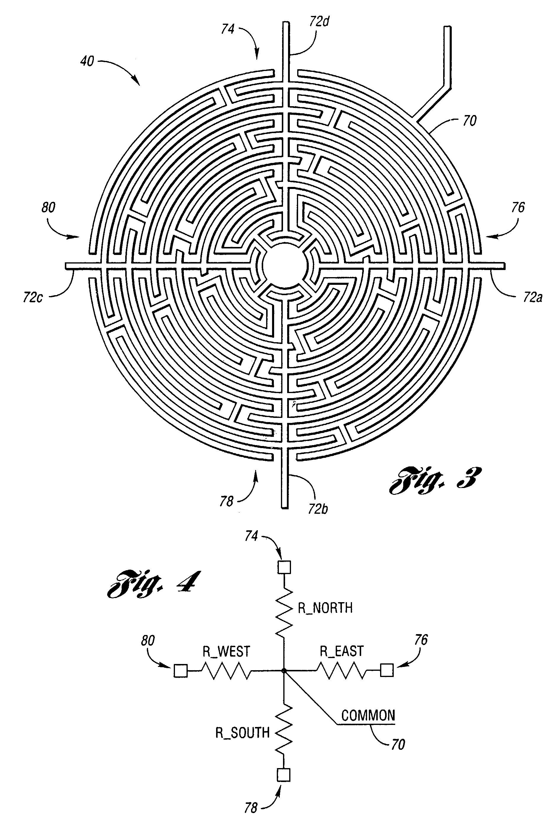
[0036]Referring to FIGS. 1a and 1b, top and bottom perspective views, respectively, illustrating a pointing device according to an embodiment of the present invention are shown. A pointing device, shown generally by 20, includes bottom substrate 22, flexible substrate 24 and top substrate 26. Top substrate 26 defines opening 28 allowing flexible substrate 24 to be depressed onto a contact area on bottom substrate 22. In some embodiments of the present invention, top substrate 26 may be eliminated.

[0037]Bottom substrate 22 defines a plurality of vias 30 passing through bottom substrate 22. The bottom side of bottom substrate 22 includes annular conductors 32 surrounding the openings for vias 30. The inside of vias 30 are also conductive. Annular conductors 32 may be directly soldered to printed circuit boards receiving pointing device 20. This eliminates the need for connective cabling, connectors, z-tape, and the like. Alternatively, vias 30 may support other types of lead elements...


PUM

PropertyMeasurementUnit
Temperatureaaaaaaaaaa
Thicknessaaaaaaaaaa
Pressureaaaaaaaaaa

Abstract

A pointing device may be directly soldered to a printed circuit board. In one embodiment, a bottom substrate defines a sensing region with a plurality of interdigitated conductive trace regions. Each trace region includes interdigitated common and sense traces. At least one via passes through the bottom substrate for each trace. Each via supports a conductive path from one trace to at least one lead element. Each lead element is solderable to a printed circuit board. A flexible substrate is constructed from a heat resistant polymer. The flexible substrate has a resistive layer deposited on a bottom side. A raised pedestal is formed on the bottom substrate top face around at least a portion of the sensing region. The pedestal separates the interdigitated conductive traces from the flexible substrate resistive layer. A button on a keypad membrane may be used to depress the flexible substrate onto the trace region.

Description

BACKGROUND OF THE INVENTION[0001]1. Field of the Invention[0002]The present invention relates to directional input devices particularly for use in portable electronic devices.[0003]2. Background Art[0004]Highly portable electronic devices, such as personal digital assistants, portable telephones, remote controls, and the like, provide increasing functionality to their users. This functionality often accompanies an increased need for information from the user. To fulfill this need, portable electronic devices incorporate mouse pointing sensors that provide directional input using a single finger, often from the same hand that holds the electronic device. In addition, many such mouse pointing sensors provide a magnitude signal in relation to force supplied by the user. This force may be applied through a joystick or a mouse button. Signals generated by such mouse pointing sensors are conditioned and processed by on-board logic to activate a pointer displayed on a graphical user interf...

Claims


Application Information

Patent Timeline
IPC IPC(8): G09G5/08G06F3/033H01H13/785H04N5/44
CPCG06F3/0338H01H13/785H04N2005/4417H01H2203/02H01H2221/012H01H2201/032H04N21/42213
Inventor BAKER, JEFFREY R.SANCHEZ, CARLOS S.TICKLE, JAMES D.
Owner INTERLINK ELECTRONICS
Why Eureka
Try Eureka