
Method of measuring a physical function using a composite function which includes the physical function and an arbitrary reference function

a composite function and physical function technology, applied in the field of measuring the attributes of a physical system, can solve the problems of wide discrepancies, lack of reliable method for measuring nonlinearity profiles, and lack of reliable procedure for measuring nonlinear profiles

Inactive Publication Date: 2006-05-23
THE BOARD OF TRUSTEES OF THE LELAND STANFORD JUNIOR UNIV
View PDF27 Cites 6 Cited by
  • Summary
  • Abstract
  • Description
  • Claims
  • Application Information

AI Technical Summary

Benefits of technology

"The present invention provides methods for measuring physical functions, nonlinearity profiles, and optical pulse temporal waveforms. These methods involve combining a physical function or nonlinearity profile with a reference function or reference nonlinearity profile to form a composite function, which is then transformed to a Fourier transform to obtain information about the physical function or nonlinearity profile. The methods can be used to measure the nonlinearity profile of a sample by placing the sample and a reference material in a specific configuration and measuring the Fourier transform magnitude of the nonlinearity profile. The methods provide a way to accurately measure nonlinearity profiles and optical pulse temporal waveforms, which can be useful in various applications such as optical communication systems."

Problems solved by technology

The field of poled silica has suffered from the lack of a common method to reliably measure the second-order optical nonlinearity profile of poled samples.
This absence of a reliable procedure for measuring nonlinearity profiles may be the reason, at least in part, for wide discrepancies in the measured magnitudes and the positions of the nonlinearity profiles of various poled systems as reported in the literature.
Consequently, for an arbitrary and unknown nonlinearity profile, the MF measurement alone is not sufficient to determine a unique solution for d33(z).
However, the previous methods do not produce a unique solution for d33(z).

Method used


Image

  • Method of measuring a physical function using a composite function which includes the physical function and an arbitrary reference function
  • Method of measuring a physical function using a composite function which includes the physical function and an arbitrary reference function
  • Method of measuring a physical function using a composite function which includes the physical function and an arbitrary reference function

Examples


Embodiment Construction

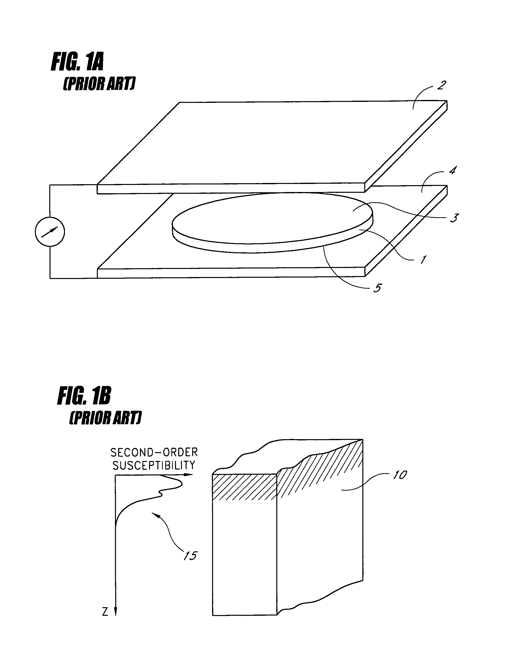
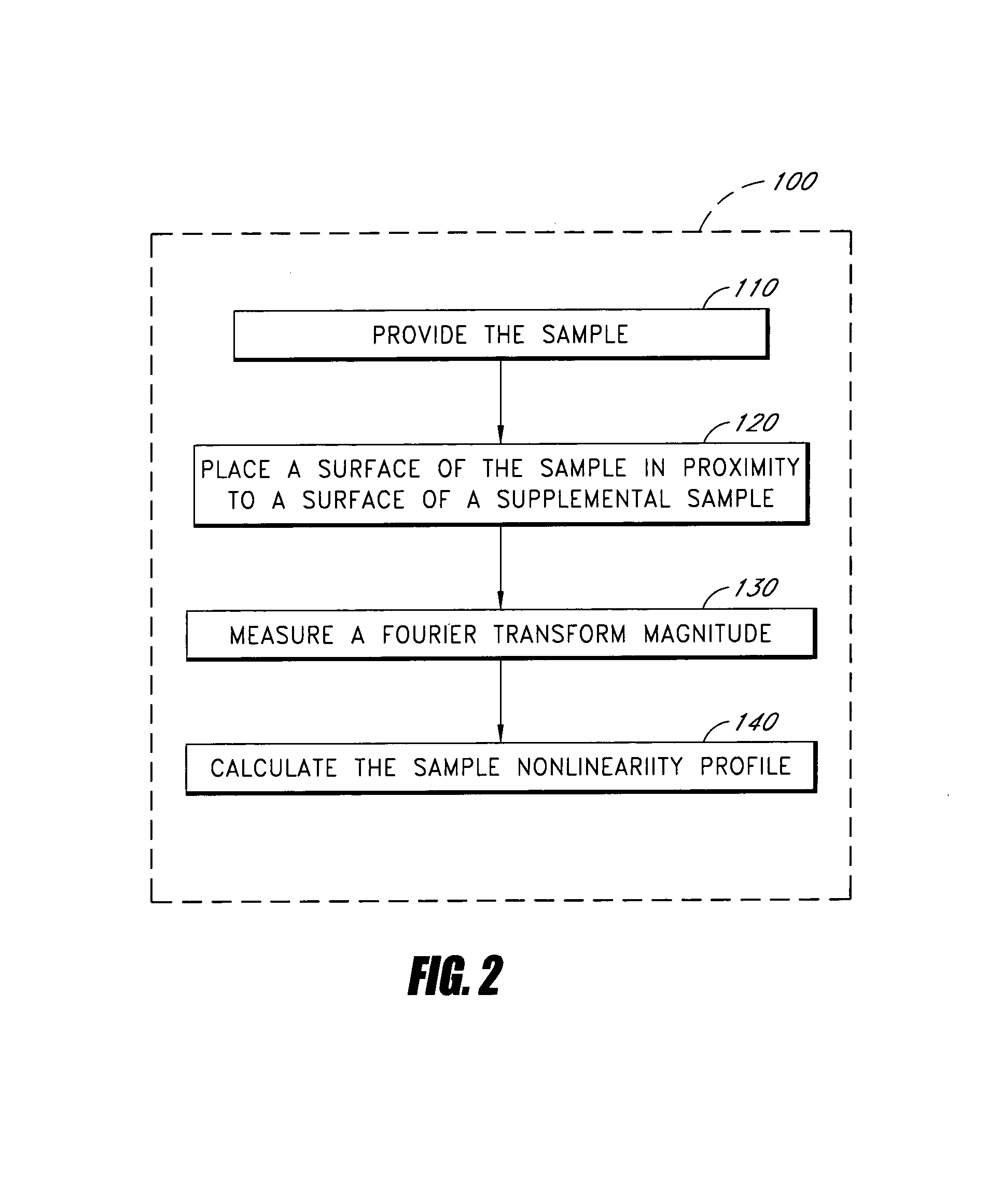
[0068]FIG. 2 is a flow diagram of a method 100 of measuring a second-order optical nonlinearity profile of a sample 10 of FIG. 1B in accordance with embodiments of the present invention. While the flow diagrams herein illustrate particular embodiments with steps in a particular order, other embodiments with different orders of steps are also compatible with the present invention.

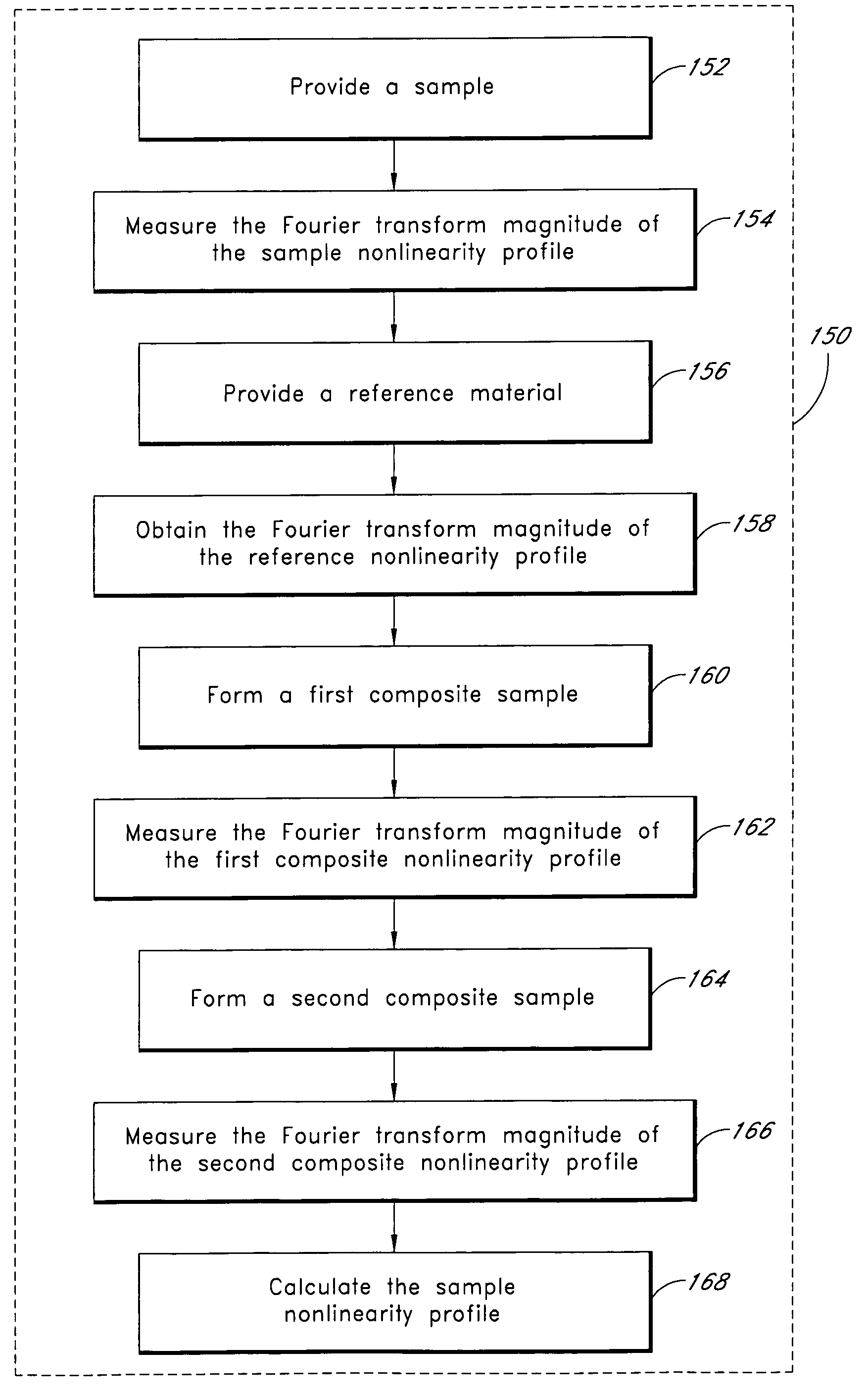
[0069]In the method 100, the sample 10 is provided in an operational block 110. The sample 10 has the second-order optical nonlinearity profile 15 to be measured. In an operational block 120, a surface of the sample 10 is placed proximate to a surface of a supplemental sample 20, as schematically illustrated in FIGS. 3A–3C and 4A–4D. As schematically illustrated in FIG. 3A, the sample 10 and supplemental sample 20 form a first composite sample 30 having an odd second-order optical nonlinearity profile 35. In an operational block 130, a Fourier transform magnitude of the odd second-order optical nonlinearity ...


PUM

PropertyMeasurementUnit
thickaaaaaaaaaa
thicknessaaaaaaaaaa
incidence angleaaaaaaaaaa

Abstract

A method for measuring a physical function forms a symmetric composite function by combining the physical function with a reference function. The method obtains a Fourier transform of the symmetric composite function. The method calculates an inverse Fourier transform of the obtained Fourier transform, wherein the calculated inverse Fourier transform provides information regarding the physical function. The physical function can be a nonlinearity profile of a sample with at least one sample surface. The physical function can alternatively by a sample temporal waveform of a sample optical pulse.

Description

CLAIM OF PRIORITY[0001]This application is a continuation-in-part of U.S. patent application Ser. No. 10 / 378,591, filed Mar. 3, 2003 now U.S. Pat. No. 6,856,393, which is a continuation-in-part of U.S. patent application Ser. No. 10 / 357,275, filed Jan. 31, 2003, which claims the benefit of and U.S. Provisional Application No. 60 / 405,405, filed Aug. 21, 2002. U.S. patent application Ser. No. 10 / 378,591, U.S. patent application Ser. No. 10 / 357,275, and U.S. Provisional Application No. 60 / 405,405, filed Aug. 21, 2002, are incorporated by reference in their entireties herein.BACKGROUND OF THE INVENTION[0002]1. Field of the Invention[0003]The present invention relates generally to the field of measuring attributes of a physical system and, more particularly, relates to methods of measuring a non-symmetric physical function.[0004]2. Description of the Related Art[0005]Various optical devices are based on induced second-order susceptibilities in silica-based glass waveguides (e.g., electro...

Claims


Application Information

Patent Timeline
Patent Type & Authority Patents(United States)
IPC IPC(8): G01N21/59G01J11/00G01N21/63
CPCG01J11/00G01N21/21G01N21/636G01N21/4788G01N2021/4735G01N2021/4723
Inventor OZCAN, AYDOGANDIGONNET, MICHEL J.F.KINO, GORDON S.
Owner THE BOARD OF TRUSTEES OF THE LELAND STANFORD JUNIOR UNIV
Learn More