Method for calibrating an interferometer apparatus, for qualifying an optical surface, and for manufacturing a substrate having an optical surface

Active Publication Date: 2006-05-23
CARL ZEISS SMT GMBH
View PDF11 Cites 21 Cited by
  • Summary
  • Abstract
  • Description
  • Claims
  • Application Information

AI Technical Summary

Problems solved by technology

Subtracting the averaged phase differences from the phase differences measured in one particular angu

Method used


Image

  • Method for calibrating an interferometer apparatus, for qualifying an optical surface, and for manufacturing a substrate having an optical surface
  • Method for calibrating an interferometer apparatus, for qualifying an optical surface, and for manufacturing a substrate having an optical surface
  • Method for calibrating an interferometer apparatus, for qualifying an optical surface, and for manufacturing a substrate having an optical surface

Examples


Embodiment Construction

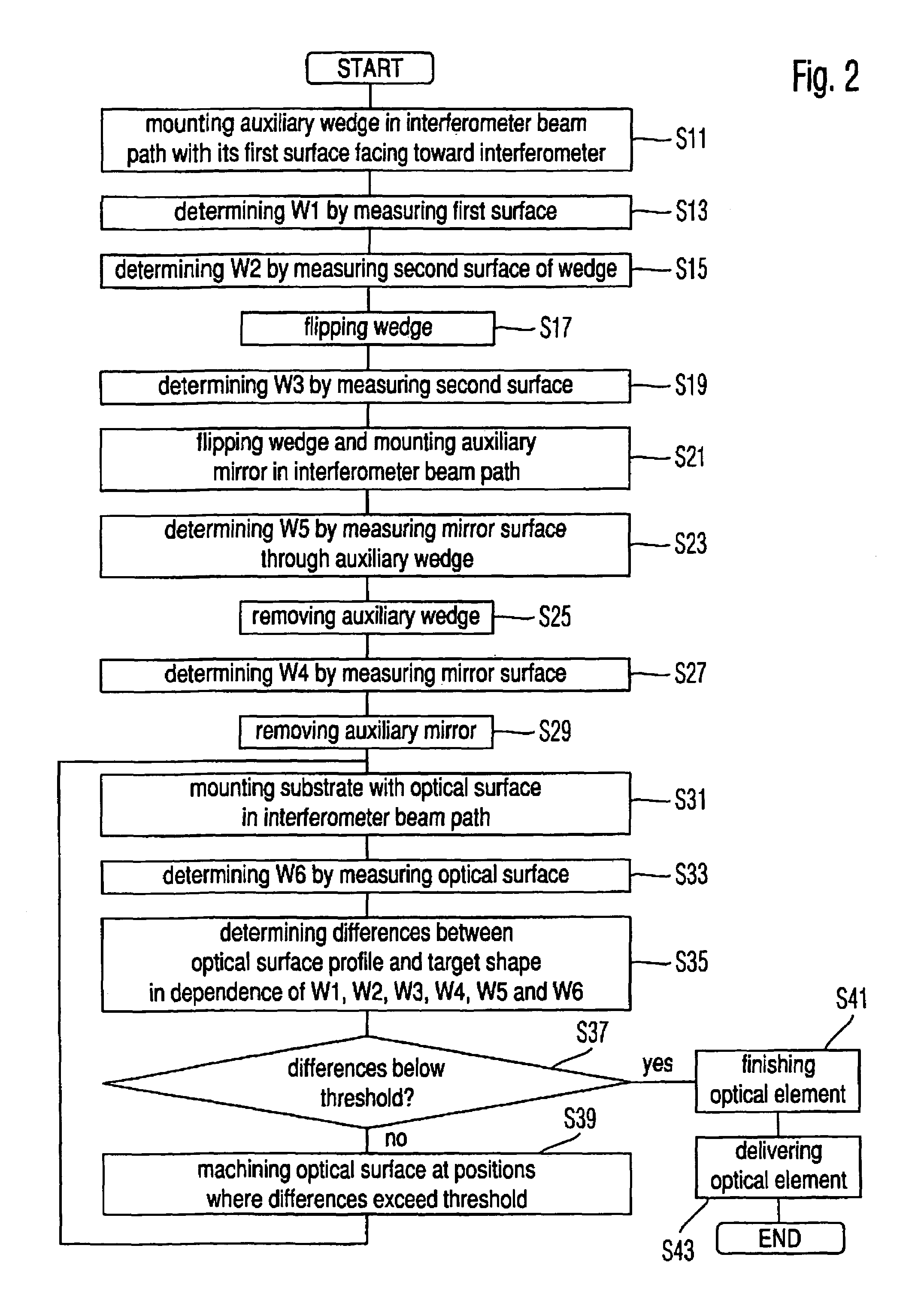
[0025]The embodiments of methods illustrated below involve interferometrically taking measurements of wavefronts generated by reflecting an incident beam provided by an interferometer apparatus from surfaces to be measured. Plural conventional interferometric methods may be used for taking such measurements. Examples of such interferometric methods are disclosed in e.g. U.S. Pat. No. 5,361,312, U.S. Pat. No. 5,982,490 and US 2002 / 0063867A1. The full disclosure of these patents and publications are incorporated herein by reference. An example of an interferometric method for measuring a first surface wherein a second surface parallel to the first surface is located in the beam path together with a reference surface is disclosed in U.S. Pat. No. 5,488,477 or Appendix A (a translation of WO 03 / 002933), wherein the full disclosure of these documents is incorporated herein by reference.

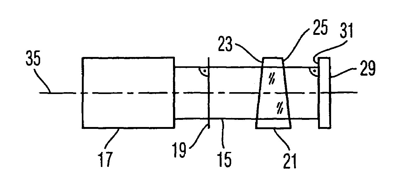
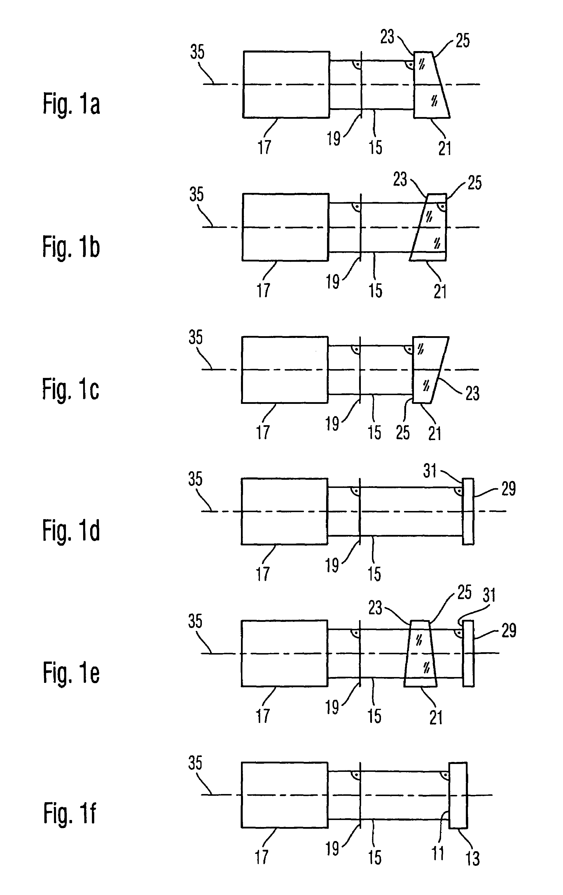
[0026]FIG. 1 illustrates a method of qualifying an optical surface 11 provided on a substrate 13 (FIG. ...


PUM


Abstract

A method for qualifying and/or manufacturing an optical surface includes:
    • arranging a first substrate having a first surface and a second surface opposite the first surface in a beam path of a first incident beam with the first surface facing towards the first incident beam, and taking an interferometric measurement of the second surface;
    • arranging the first substrate in the beam path of the first incident beam with the second surface facing towards the first incident beam, and taking an interferometric measurement of the second surface;
    • arranging a third surface of a second substrate in a beam path of a second incident beam, and taking an interferometric measurement of the third surface;
    • arranging the third surface of the second substrate and the first substrate in the beam path of the second incident beam, and taking an interferometric measurement of the third surface.

Description

FIELD OF THE INVENTION[0001]The present invention relates to the field of measuring and manufacturing optical surfaces. In particular the invention relates to a method for calibrating an interferometer apparatus for measuring an optical surface and / or a method for qualifying the optical surface by using the apparatus and / or a method for manufacturing an optical surface by using the interferometer apparatus.BACKGROUND OF THE INVENTION[0002]The substrate having the optical surface is, for example, an optical component such as an optical lens or an optical mirror used in optical systems, such as telescopes used in astronomy, or systems used for imaging structures of a mask (“reticle”) onto a radiation sensitive substrate (“resist”) in a lithographic method. The success of such an optical system is substantially determined by the precision with which the optical surface can be machined or manufactured to have a target shape. In such manufacture it is necessary to compare the shape of th...

Claims


Application Information

Patent Timeline
IPC IPC(8): G01B9/02
CPCG01B11/2441G01M11/005G01M11/025G01B9/02072G03F7/70591G01B9/02039G01B9/02057G01M11/0271
Inventor FREIMANN, ROLFDORBAND, BERND
Owner CARL ZEISS SMT GMBH
Why Eureka
Try Eureka