
Electronic equipment

a technology of electronic equipment and insulating conductors, which is applied in the direction of power cables, cables, insulated conductors, etc., can solve the problems of not giving adequate consideration to the loading and unloading of wiring boards, unable to provide a mechanism appropriate for corrective action, and the fan high speed rotation problem

Inactive Publication Date: 2006-05-23
HITACHI LTD
View PDF16 Cites 42 Cited by
  • Summary
  • Abstract
  • Description
  • Claims
  • Application Information

AI Technical Summary

Benefits of technology

[0020]Accordingly, it is an object of the present invention to provide reliable electronic equipment that is free from the above mentioned problem.
[0025]Preferably, the diameter of the second piping becomes smaller from upstream to downstream in the circulation of the fluid.

Problems solved by technology

If cooling efficiency is increased, a noise problem due to high speed rotation of the fan arises.
No sufficient consideration is given to the loading and unloading of the wiring board.
The server in a network system has difficulty in the removal of a wiring board in need of replacement and the loading of another wiring board with safety in the casing particularly in the middle of operation of the electronic apparatus.
However, the above conventional arts provide no mechanism appropriate for allowing a corrective action to take without stopping the operation of the system.
The duplication of the fluid circulation type cooling device in each electronic apparatus raises space and cost problems.

Method used


Image

  • Electronic equipment
  • Electronic equipment
  • Electronic equipment

Examples


Embodiment Construction

[0048]The present invention achieves an efficient cooling device which requires no duplication of the fluid circulation cooling device in each electronic apparatus. Embodiments of the present invention will now be discussed.

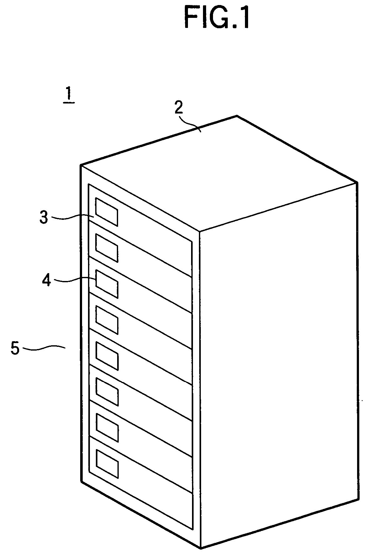
[0049]FIG. 1 is a perspective view of electronic equipment of one preferred embodiment of the present invention. As shown, electronic equipment 1 is a server. A cabinet 2 is the external housing of the electronic equipment 1. The cabinet 2 houses a plurality of electronic units 3 stacked (eight stacks of electronic apparatus units 3 are installed in this preferred embodiment). A display 4 is arranged on the front side 5 of each electronic apparatus unit 3. The display 4 presents an indication of whether or not the electronic apparatus unit 3 is powered and an indication of a failure if any cooling device fails.

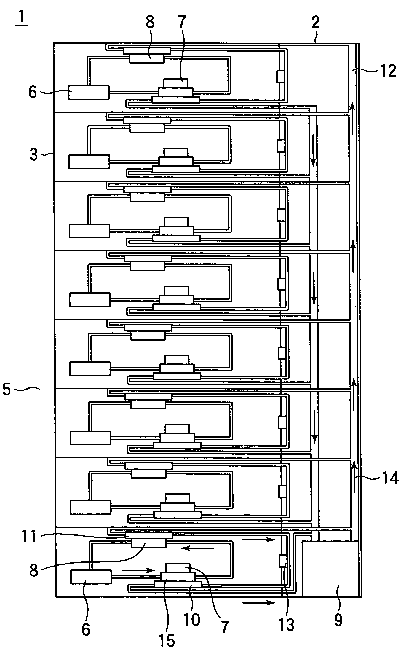
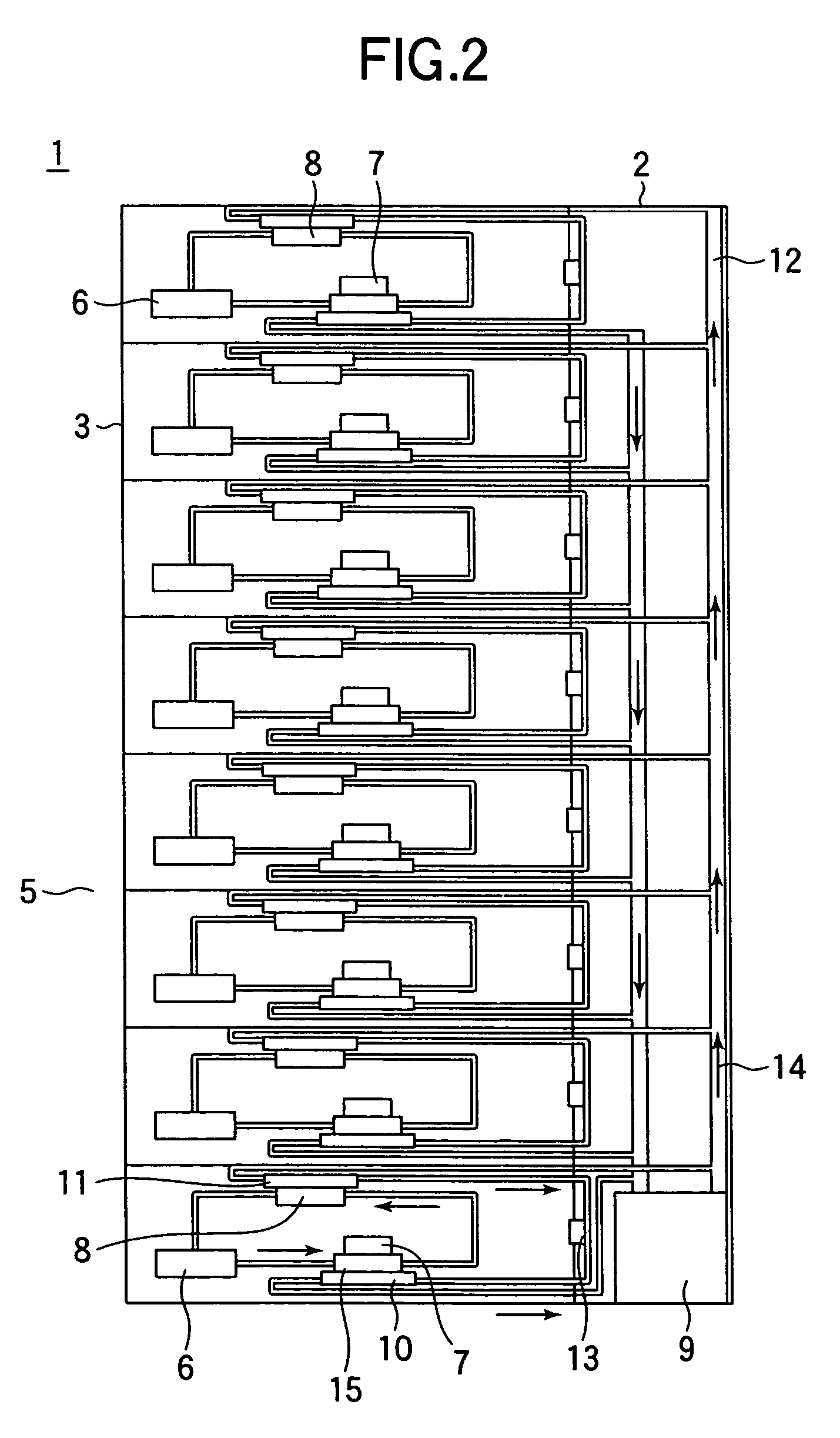
[0050]FIG. 2 is an elevation section of a cooling system installed in the electronic equipment of FIG. 1, viewed from the side thereof.

[0051]As shown, the ...


PUM


Abstract

An electronic module which is detachably mounted on electronic equipment. The electronic module includes a board having a heat generator mounted on a surface thereof, and a cooling jacket which is integrally attached to the electronic module. The cooling jacket is thermally coupled to the heat generator and has a passage of a cooling fluid therewithin.

Description

CROSS REFERENCE TO RELATED APPLICATION[0001]This is a continuation of U.S. application Ser. No. 10 / 621,647, filed Jul. 18, 2003, now U.S. Pat. No. 6,807,056 the subject matter of which is incorporated by reference herein.BACKGROUND OF THE INVENTION[0002]1. Field of the Invention[0003]The present invention relates to electronic equipment having a cooling device circulating a cooling fluid.[0004]2. Description of the Related Art[0005]Electronic equipment includes mainframe computers and medium-scale server computers used by corporates such as banks, in addition to widely used personal computers and desk-top computers.[0006]Server computers as electronic equipment are typically connected to a plurality of terminals. Such electronic equipment is formed of a plurality of stacked electronic devices, which run software programs for calculation or retrieving mail data.[0007]Depending on the purposes of applications, the user must replace, add, or remove the electronic devices, each running ...

Claims


Application Information

Patent Timeline
Patent Type & Authority Patents(United States)
IPC IPC(8): H05K7/20G06F1/20
CPCG06F1/20H05K7/20781G06F2200/201
Inventor KONDO, YOSHIHIROOHASHI, SHIGEOMINAMITANI, RINTARONAGANAWA, TAKASHIYOSHITOMI, YUJINAKANISHI, MASATOSASAKI, YASUHIKONAKAGAWA, TSUYOSHISUZUKI, OSAMUMATSUSHITA, SHINJIYAMADA, YASUNORI
Owner HITACHI LTD
Learn More