Eureka AIR delivers breakthrough ideas for toughest innovation challenges, trusted by R&D personnel around the world.

Telephone line interface circuit and method

a telephone line and interface circuit technology, applied in the direction of electrical equipment, substation equipment, interconnection arrangements, etc., can solve the problems of low signal strength of transmitted signal, poor signal-to-noise ratio, and high implementation cost of transformer hybrid circuits on integrated circuits

Inactive Publication Date: 2006-05-23
STMICROELECTRONICS SRL
View PDF8 Cites 6 Cited by
  • Summary
  • Abstract
  • Description
  • Claims
  • Application Information

AI Technical Summary

Benefits of technology

[0008]The present invention overcomes the shortcomings in prior systems and thereby satisfies a significant need for a hybrid circuit for a modem or other device having a transmitter and a receiver associated with a telecommunications line, such as a telephone line on which information is communicated in two directions using the ADSL protocol. The hybrid circuit substantially cancels signals generated by the modem transmitter from appearing at the input of the modem receiver and filters signals, such as echo signals, at unwanted frequencies so that the receiver primarily receives at its input signals transmitted from a remote device.

Problems solved by technology

Although somewhat effective in isolating the modem receiver path from the modem transmitter path, the transformer hybrid circuit is expensive to implement on an integrated circuit.
The resistive divider circuit, however, degrades the signal strength of the signal transmitted over the telecommunications line and itself generates an appreciable amount of thermal noise due to the presence of resistors therein, thereby providing a relatively poor signal-to-noise ratio.
Consequently, for handling communication over a relative high loss line, such as a twisted pair telephone line, a resistive divider hybrid circuit is not a perfect solution.
As is well known, such filters are quite expensive to implement.

Method used


Image

  • Telephone line interface circuit and method
  • Telephone line interface circuit and method
  • Telephone line interface circuit and method

Examples


Embodiment Construction

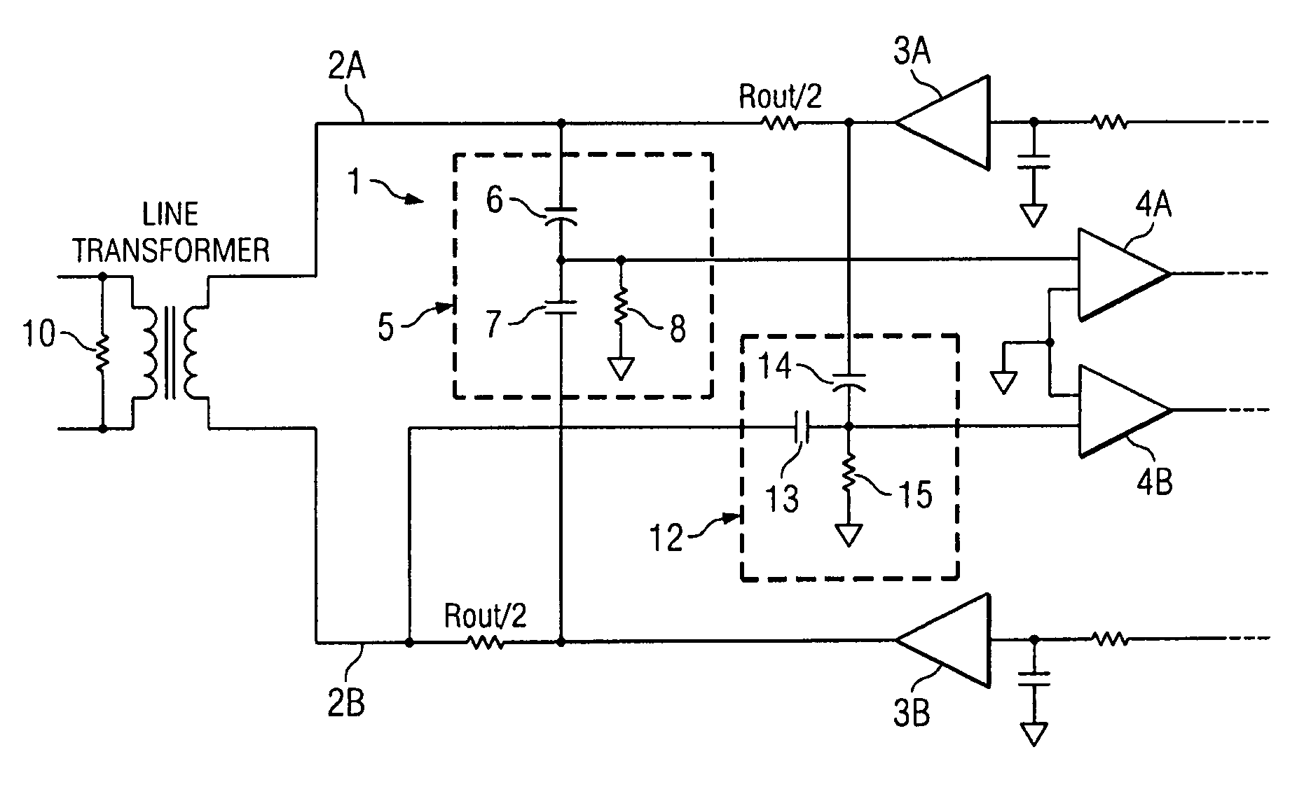
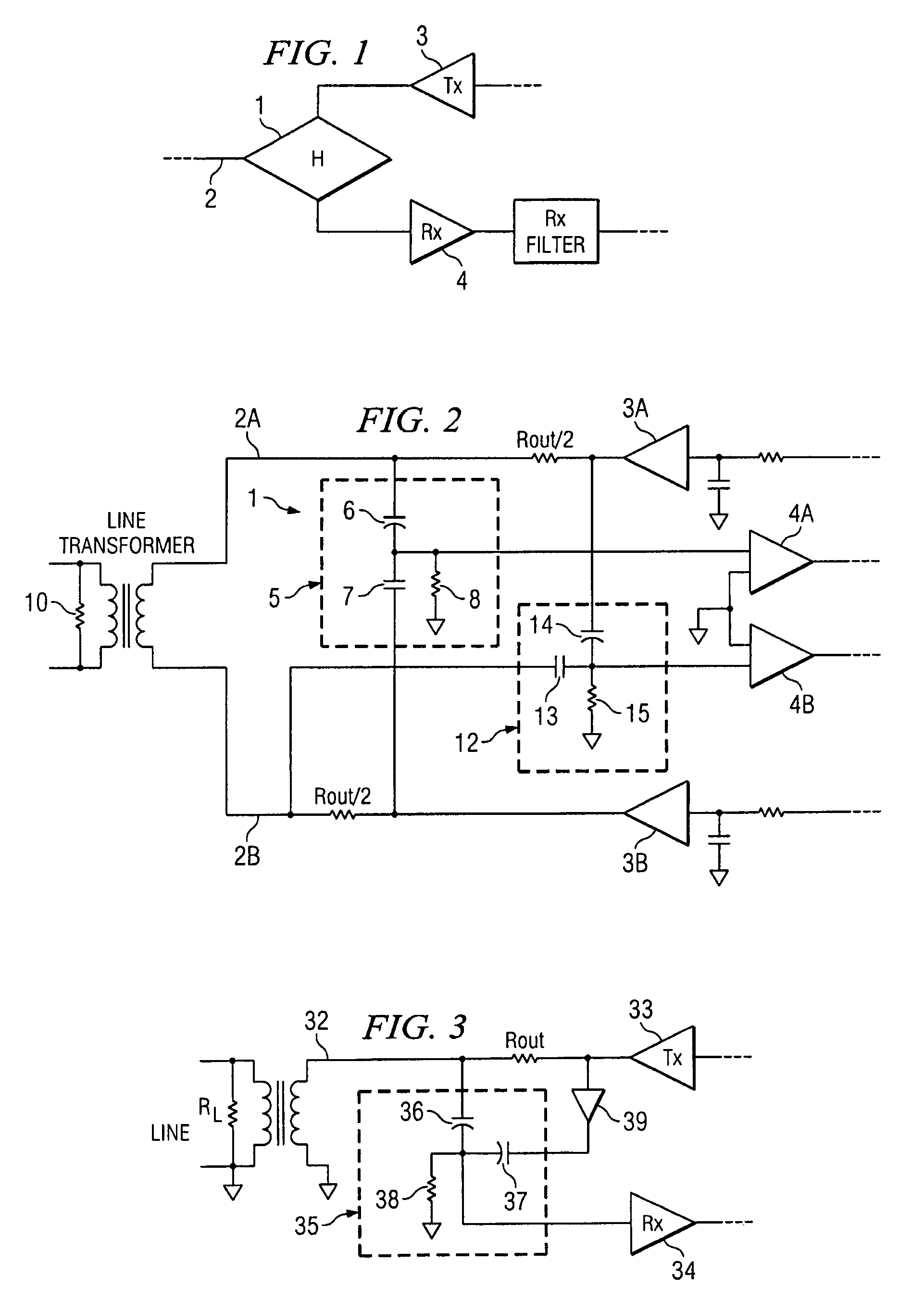
[0018]Referring to FIGS. 1 and 2, there is shown a hybrid circuit 1 according to a preferred embodiment of the present invention. Hybrid circuit 1 is coupled to one end of a telecommunications line 2 over which information is communicated. Hybrid circuit 1 cooperates with transmitter 3 and receiver 4, each of which is coupled to telecommunications line 2. Transmitter 3 and receiver 4 respectively transmit and receive information over telecommunications line 2.

[0019]It is understood that hybrid circuit 1, transmitter 3 and receiver 4 may together form a modem or portion thereof. Alternatively, hybrid circuit 1 may be a stand-alone device.

[0020]In general terms, hybrid circuit 1 is electrically connected to transmitter 3, receiver 4 and telecommunication line 2 to substantially isolate the input of receiver 4 from signals generated by transmitter 3. Hybrid circuit 1 isolates the input of receiver 4 in part by canceling common signals appearing at the output of transmitter 3 and on tel...


PUM


Abstract

A hybrid circuit is disclosed for effectively communicating information over a telecommunications line to which a transmitter and receiver are connected. The hybrid circuit is configured as a filter for filtering at the receiver input signals at predetermined frequencies appearing on the transmitter output and the telecommunications line. The filter circuit additionally forms a capacitive divider for scaling signals appearing at the transmitter output and canceling the scaled signals at the receiver input with related signals appearing on the telecommunications line. In one embodiment of the present invention for communicating using the ADSL protocol, the filter circuit is a first order high pass filter.

Description

BACKGROUND OF THE INVENTION[0001]1. Technical Field of the Invention[0002]The present invention relates to an interface circuit for a telecommunications line, and particularly to a hybrid circuit for communicating over a telephone line.[0003]2. Background of the Invention[0004]Hybrid circuits have been used in modems or other communication devices to isolate the modem receiver from being affected by transmissions of the modem transmitter. Known hybrid circuits include a transformer circuit utilizing at least two transformers. Although somewhat effective in isolating the modem receiver path from the modem transmitter path, the transformer hybrid circuit is expensive to implement on an integrated circuit.[0005]A second known hybrid circuit is a resistive divider circuit implemented in a resistor bridge configuration. The resistive divider circuit, however, degrades the signal strength of the signal transmitted over the telecommunications line and itself generates an appreciable amount...

Claims


Application Information

Patent Timeline
IPC IPC(8): H04M1/00H04M9/00H04B1/52H04B1/58H04M1/58H04B3/03H04M11/00
CPCH04B1/586
Inventor VARELJIAN, ALBERT
Owner STMICROELECTRONICS SRL
Why Eureka
Eureka Blog
Learn More