Speaker system, mobile terminal device, and electronic device

a technology of mobile terminal and electronic device, which is applied in the direction of diaphragm construction, electrical transducers, substation equipment, etc., can solve the problem of user's sense of unnaturalness, and achieve the effect of increasing the degree of location freedom

Active Publication Date: 2006-05-23
PANASONIC CORP
View PDF10 Cites 98 Cited by
  • Summary
  • Abstract
  • Description
  • Claims
  • Application Information

AI Technical Summary

Benefits of technology

[0044]Thus, the invention described herein makes possible the advantages of providing (1) a speaker system in which the position where an image is displayed to the user is the same a

Problems solved by technology

For example, when the electronic device or the mobile terminal device is used as a video telephone, the user has a sense of unnaturalness

Method used


Image

  • Speaker system, mobile terminal device, and electronic device
  • Speaker system, mobile terminal device, and electronic device
  • Speaker system, mobile terminal device, and electronic device

Examples


example 1

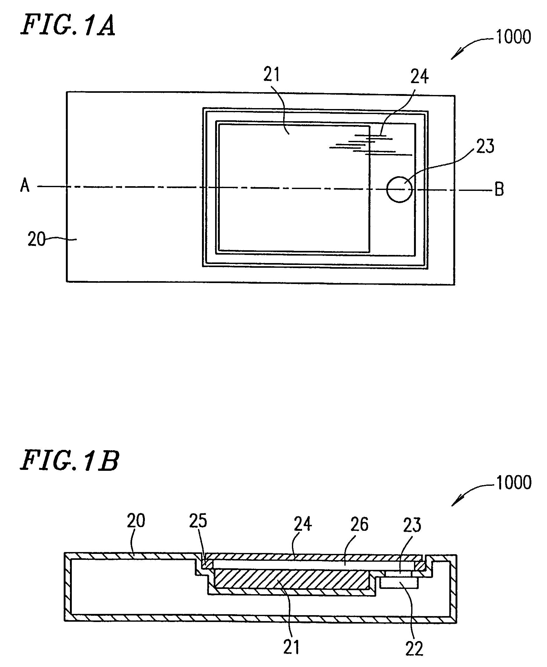
[0084]A speaker system 1000 according to a first example of the present invention will be described with reference to FIGS. 1A and 1B. FIG. 1A is a plan view of the speaker system 1000, and FIG. 1B is a cross-sectional view of the speaker system 1000 taken along chain line A–B shown in FIG. 1A.

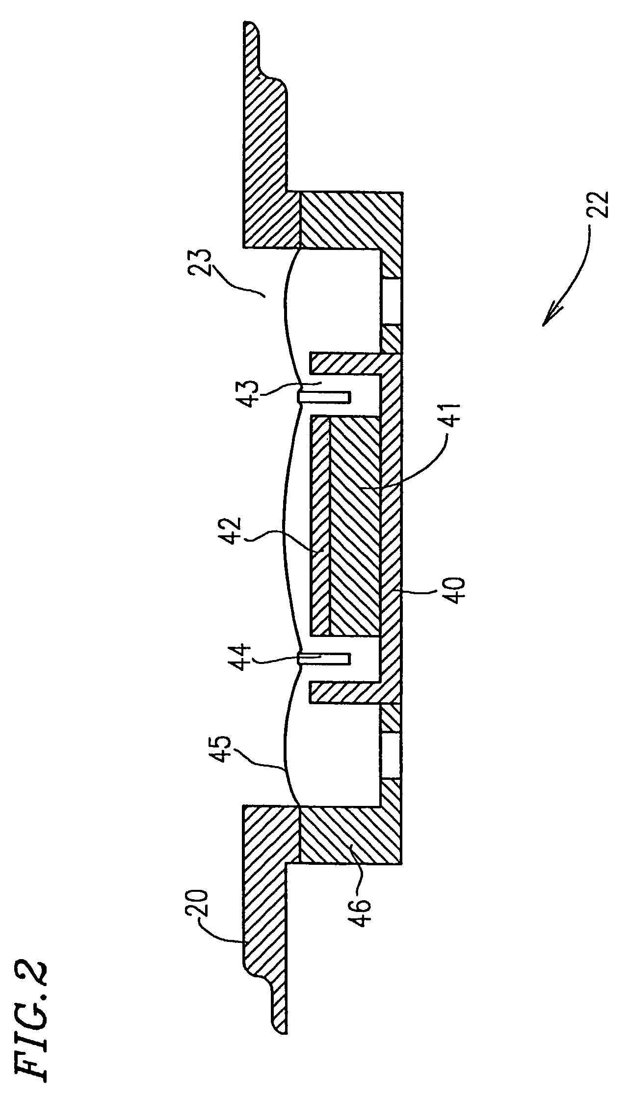
[0085]The speaker system 1000 includes a display panel 21 for displaying an image, a transparent panel 24 located so as to allow an image displayed in the display panel 21 to be viewed through the transparent panel 24, an electric-mechanical-acoustic-transducer 22 having a diaphragm 45 (FIG. 2) for vibrating the diaphragm 45 in accordance with an electric signal so as to output a sound, an elastic member 25 connected to a peripheral portion of the transparent panel 24, and a housing 20 for supporting the transparent panel 24 and the display panel 21.

[0086]The speaker system 1000 has a space 26 between the display panel 21 and the transparent panel 24. The space 26 is preferably a closed space....

example 2

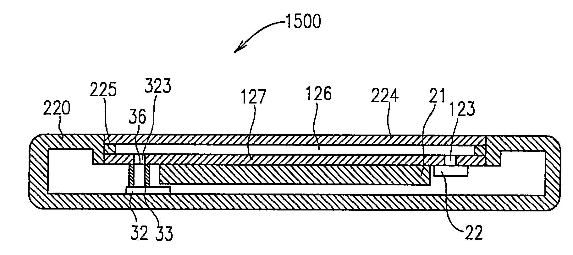
[0103]A speaker system 1100 according to a second example of the present invention will be described with reference to FIGS. 4 and 5. FIG. 4 is a plan view of the speaker system 1100, and FIG. 5 is a cross-sectional view of the speaker system 1100 taken along chain line C–D shown in FIG. 4.

[0104]The speaker system 1100 includes a display panel 21 for displaying an image, a transparent panel 224 located so as to allow an image displayed in the display panel 21 to be viewed through the transparent panel 224, a transparent substrate 227 located between the display panel 21 and the transparent panel 224 so as to allow an image displayed in the display panel 21 to be viewed through the substrate 227, an electric-mechanical-acoustic-transducer 22 having a diaphragm 45 (FIG. 2) for vibrating the diaphragm 45 in accordance with an electric signal so as to output a sound, a spacer (elastic member) 225 for connecting a peripheral portion of the transparent panel 224 and a peripheral portion o...

example 3

[0121]A speaker system 1200 according to a third example of the present invention will be described with reference to FIGS. 7A and 7B. FIG. 7A is a plan view of the speaker system 1200, and FIG. 7B is a cross-sectional view of the speaker system 1200 taken along chain line E–F shown in FIG. 7A.

[0122]The speaker system 1200 includes a display panel 21 for displaying an image, a transparent panel 34 located so as to allow an image displayed in the display panel 21 to be viewed through the transparent panel 34, an electric-mechanical-acoustic-transducer 32 having a diaphragm 52 (FIG. 8) for vibrating the diaphragm 52 in accordance with an electric signal so as to output a sound, an acoustic pipe 33 connected to the electric-mechanical-acoustic-transducer 32, and a housing 20 for supporting the transparent panel 34 and the display panel 21.

[0123]The speaker system 1200 has a space 37 between the display panel 21 and the transparent panel 34. The space 37 is preferably a closed space. Th...


PUM


Abstract

A speaker system includes a display panel for displaying an image; a transparent panel provided such that the image displayed in the display panel is viewed through the transparent panel; an electric-mechanical-acoustic-transducer having a diaphragm for outputting a sound by vibrating the diaphragm in accordance with an electric signal; and an acoustic signal transfer member for transferring the sound output from the electric-mechanical-acoustic-transducer to a space provided between the display panel and the transparent panel. The transparent panel is allowed to be vibrated by the sound transferred to the space from the electric-mechanical-acoustic-transducer via the acoustic signal transfer member.

Description

BACKGROUND OF THE INVENTION[0001]1. Field of the Invention[0002]The present invention relates to a speaker system, and a mobile terminal device and an electronic device including the speaker system.[0003]2. Description of the Related Art[0004]With reference to FIG. 27, a conventional cellular telephone 15 will be described. Japanese Laid-Open Publication No. 8-275293 discloses a speaker system for vibrating a housing of a cellular phone by a driver directly attached to the housing so as to output a vibration or sound.[0005]The cellular phone 15 includes a housing 10, an antenna 11, a sound board 12 which is thinner in a rear peripheral portion than the rest thereof, a driver 13 provided on a rear surface of the sound board 12, and a character display panel 14 provided on a front surface of the housing 10 adjacent to the sound board 12.[0006]An operation of the cellular phone 15 will be described. When an electric signal is applied to the driver 13, the vibration of the driver 13 is ...

Claims


Application Information

Patent Timeline
IPC IPC(8): H04R1/02H04R1/00H04R1/20H04R25/00H04M1/03H04R7/04
CPCH04M1/03H04R9/046H04R1/028H04M1/035H04R2499/15H04R2499/11
Inventor SAIKI, SHUJIUSUKI, SAWAKOKONISHI, SHUHEI
Owner PANASONIC CORP
Why Eureka
Try Eureka