Barcode detection system

a detection system and barcode technology, applied in the field of barcode detection, can solve the problems of requiring a substantial amount of time to accumulate and operate on data, affecting the accuracy of data acquisition, so as to achieve accurate determination, reduce and compress the effect of data

Active Publication Date: 2006-05-23
SICK AUTO IDENT
View PDF8 Cites 30 Cited by
  • Summary
  • Abstract
  • Description
  • Claims
  • Application Information

AI Technical Summary

Benefits of technology

[0004]It is a further object of this invention to provide such an improved method and system for barcode detection which is faster and uses less hardware.
[0005]It is a further object of this invention to provide such an improved method and system for barcode detection which more definitively and accurately determines the location and orientation of a barcode.
[0006]It is a further object of this invention to provide such an improved method and system for barcode detection which reduces and compresses the data on which it must operate.
[0007]The invention results from the realization that detection of a barcode in an image including location and / or orientation can be effected more quickly and effectively with less hardware by examining the image in a plurality of grids, obtaining a profile of the image along the edge of the grid, determining the number of transitions on the profile of each side, and comparing the number of transitions on each adjacent pair of sides with the number of transitions on the opposing adjacent pair of sides, and identifying a potential barcode data bearing grid when the count of transitions on one pair of adjacent sides matches the count of transitions on the opposing one and the further realization that by obtaining a profile of the image in a circular pattern in a lesser, sub-grid, dividing the circular pattern into a number of pairs of opposing semi-circular patterns and comparing the semi-circular pattern of profiles, the orientation of the barcode data bearing grid can be ascertained as a function of the orientation of the best match pair of semi-circular profile patterns.

Problems solved by technology

One of the shortcomings of this approach is that most of the data captured by the camera in such a case is a useless image of the conveyor and the non-barcode bearing areas of the parcels moving along the conveyor: only a small percentage of the image data includes the barcodes.
This approach, like the earlier one, employs significant hardware and requires a substantial amount of time to accumulate and operate on the data.

Method used


Image

  • Barcode detection system
  • Barcode detection system
  • Barcode detection system

Examples


Embodiment Construction

[0039]Aside from the preferred embodiment or embodiments disclosed below, this invention is capable of other embodiments and of being practiced or being carried out in various ways. Thus, it is to be understood that the invention is not limited in its application to the details of construction and the arrangements of components set forth in the following description or illustrated in the drawings.

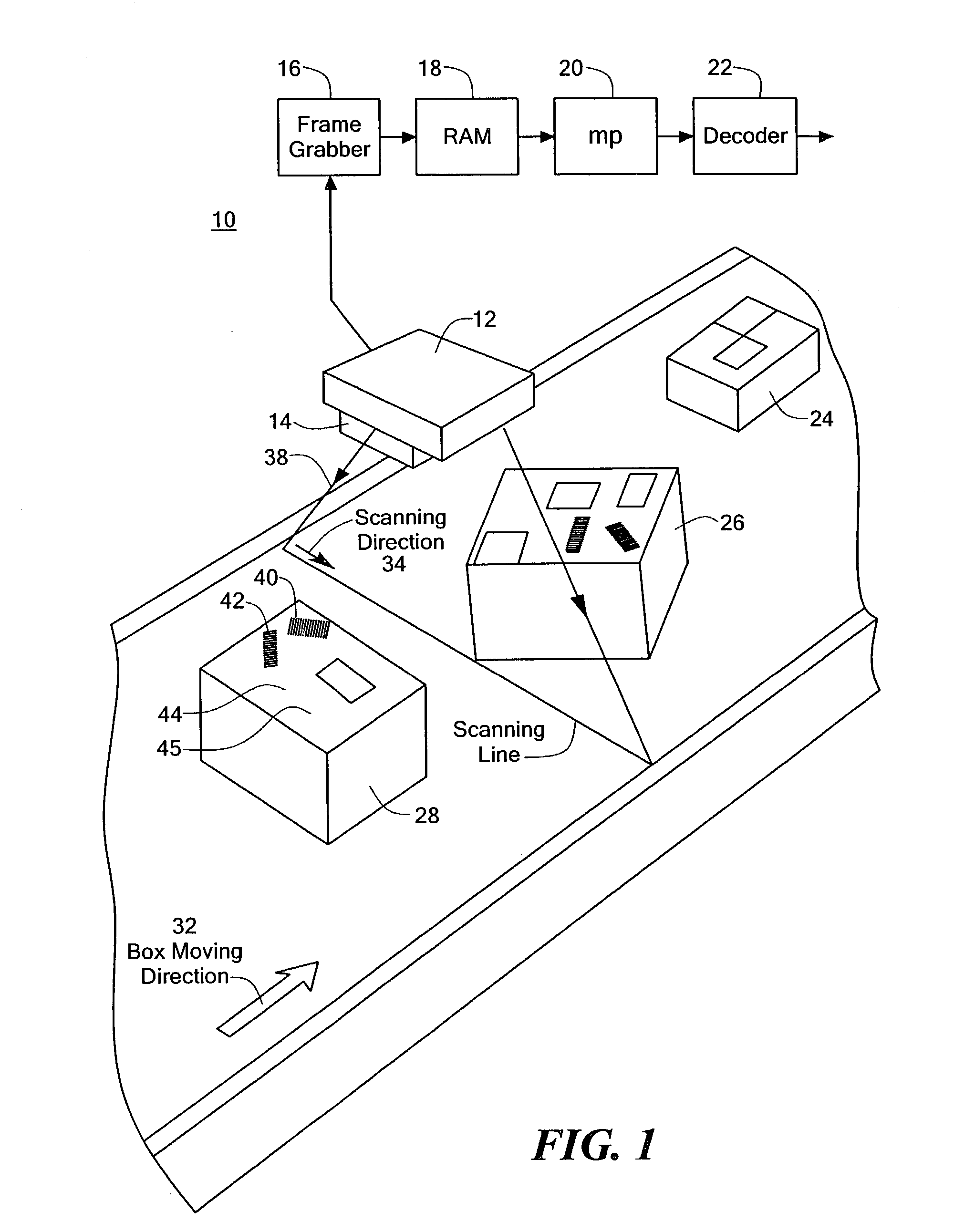
[0040]There is shown in FIG. 1 a barcode detection system 10 including camera 12 with optics 14, frame grabber 16, random access memory 18, microprocessor 20, and decoder 22. As packages, such as boxes 24, 26, and 28 are moved along by conveyor 30 in the direction of arrow 32, they are scanned in the direction of arrow 34 along scanning line 36 from optics 14. Each package, as exemplified by box 28, includes on its top 45 one or more barcodes 40, 42 and a variety of extraneous information such as labels, logos, directions 44 which add to and complicate the job of detecting the barcodes them...


PUM


Abstract

A barcode detection device is disclosed which captures an image; examines the image in a plurality of grids; obtains a profile of the image along the sides of the grids; determines the number of transitions in the profile of each side; compares the number of transitions in each adjacent pair of sides with the number of transitions in the opposing adjacent pair of sides, respectively, and identifies a potential barcode data bearing grid when the count of transitions on one pair of adjacent sides matches the count of transitions on the opposing pair of adjacent sides.

Description

FIELD OF THE INVENTION[0001]This invention relates to a method and system for barcode detection including barcode position and orientation.BACKGROUND OF THE INVENTION[0002]A barcode is a machine readable symbol made up of parallel solid lines of bars and spaces of varying width. The bars and spaces form alternate light and dark areas representing a digital code that contains the information represented by the barcode symbol. The digital code is translated to alpha numeric characters which may represent information about the item bearing the barcode label such as price, date, manufacturer and other information. Barcodes are typically read by scanning with a small spot of light. The reflected light is sensed by a photosensitive element as the spot sweeps across the barcode surface. The change in reflectance caused by the black and white bars and spaces varies the intensity of the reflected light which serves as a representation of the barcode symbol. In one type of barcode reader a tw...

Claims


Application Information

Patent Timeline
Patent Type & Authority Patents(United States)
IPC IPC(8): G06K9/18G06V30/224G06K7/10G06K7/14
CPCG06K7/14G06K7/10861
Inventor BIAN, LONG XIANGSWEENEY, JR., WALTER P.
Owner SICK AUTO IDENT
Why Eureka
Try Eureka