Processor emulator transferring data with emulation controller continuously without interruption
a technology of emulation controller and processor emulator, which is applied in the direction of detecting faulty computer hardware, error detection/correction, instruments, etc., can solve the problems of requiring thousands or hundreds of thousands of shift operations to fully test the circuit, the test time for ic manufacturing testing is extremely long, and the pattern entering and out of the circuit being tested is time-consuming. , to achieve the effect of reducing the test access tim
- Summary
- Abstract
- Description
- Claims
- Application Information
AI Technical Summary
Benefits of technology
Problems solved by technology
Method used
Image
Examples
case 1
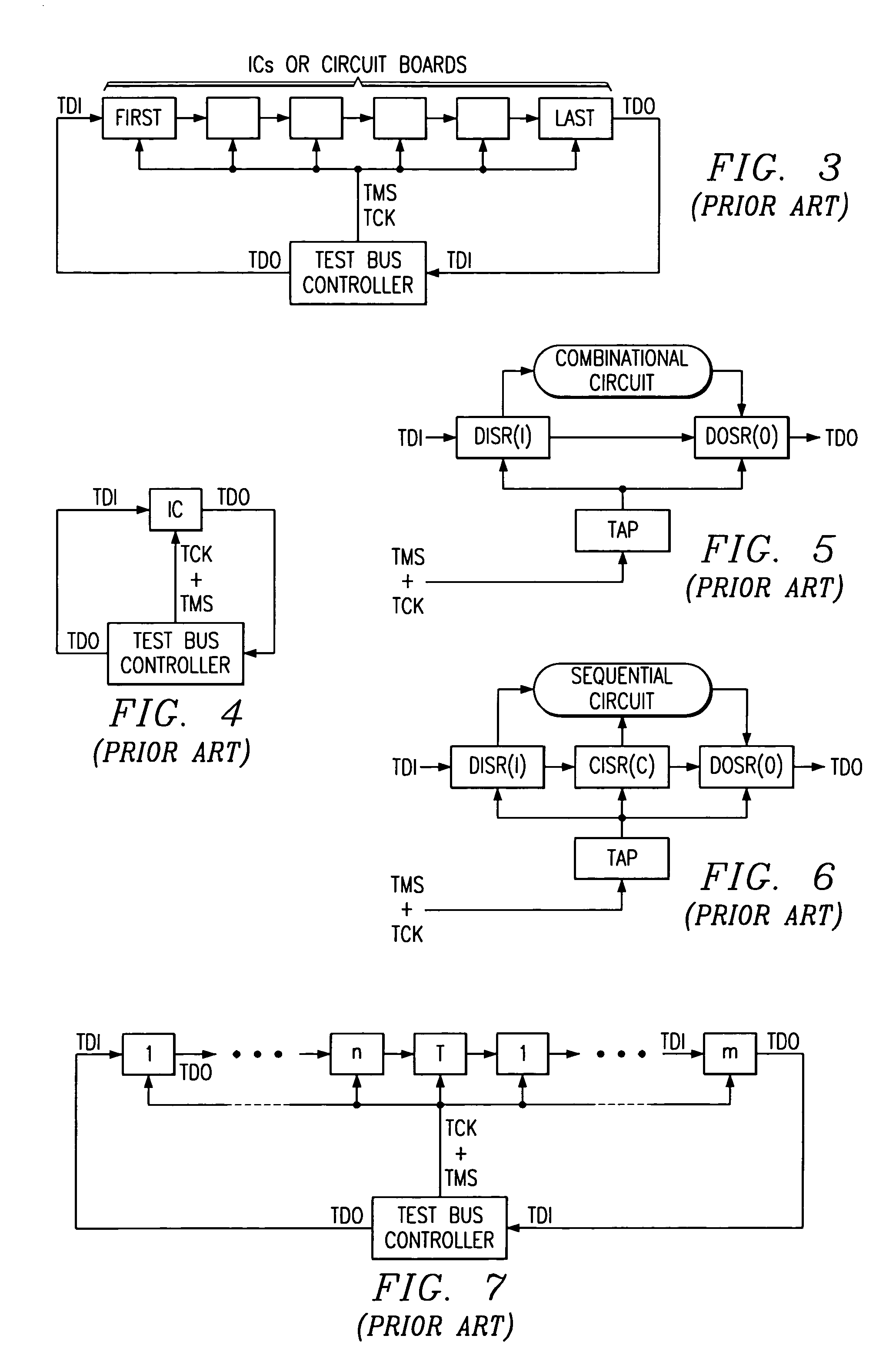
[0126 is illustrated in FIG. 10a and occurs when the length of the DISR and DOSR are exactly the same. In FIG. 10a, the DISR and DOSR are both 4-bits in length. During test operations, the BIOS inputs shift in and update (UP) control into DISR and capture (CP) and shift out control to the DOSR while the TAP is in the SHIFTDR state. The test involves repeating the steps of; (1) shifting a 4-bit test pattern from the test bus controller into the DISR, (2) updating the 4-bit test pattern and inputting it to the combinational circuit, (3) capturing the 4-bit output response from the combinational circuit into the DOSR, and (4) shifting out the captured 4-bit response pattern to the test bus controller for processing.
[0127]The update control input to the DISR from the BIOS occurs during the TCK bus cycle following the TCK bus cycle that shifts the last serial test bit (bit1) into the DISR. The capture control input to the DOSR from the BIOS occurs on the TCK bus cycle following the updat...
case 2
[0128 is illustrated in FIG. 10b and occurs when the length of the DISR is greater than the length of the DOSR. In FIG. 10b, the DISR is 4-bits in length and the DOSR is 2-bits in length. Testing is accomplished the same way as described in case 1, and involves repeating the steps of; (1) shifting a 4-bit test pattern from the test bus controller into the DISR, (2) updating the 4-bit test pattern and inputting it to the combinational circuit, (3) capturing the 2-bit output response from the combinational circuit into the DOSR, and (4) shifting out the captured 2-bit response pattern plus two bits of dummy response patterns (X) shifted into the DOSR from a fixed logic level input to the serial input of the DOSR. As the 2-bit response pattern is shifted out of the DOSR, the fixed dummy bits (X) are shifted into the 2-bit DOSR and shifter out to the test bus controller immediately after the 2-bit response pattern. The test bus controller receiving the serial 2-bit response pattern and ...
case 3
[0130 is illustrated in FIG. 10c and occurs when the length of the DISR is less than the length of the DOSR. In FIG. 10c, the DISR is 2-bits in length and the DOSR is 4-bits in length. Testing is accomplished the same way as described in case 1 except that the BIOS additionally inputs control to the DISR to provide wait states during the shift in process. Testing of case 3 involves repeating the steps of; (1) shifting a 2-bit test pattern from the test bus controller into the DISR, (2) suspending the shift in operation to the DISR for two wait states or TCK bus cycles, (3) updating the 2-bit test pattern and inputting it to the combinational circuit, (4) capturing the 4-bit output response from the combinational circuit into the DOSR, and (5) shifting out the captured 4-bit response pattern to the test bus controller for processing. The wait states are represented by dummy bits (X) which are inserted by the test bus controller, but ignored by the BIOS during step (2) above. It shoul...
PUM
 Abstract
Description
Claims
Application Information
 - R&D
- Intellectual Property
- Life Sciences
- Materials
- Tech Scout
- Unparalleled Data Quality
- Higher Quality Content
- 60% Fewer Hallucinations
Browse by: Latest US Patents, China's latest patents, Technical Efficacy Thesaurus, Application Domain, Technology Topic, Popular Technical Reports.
© 2025 PatSnap. All rights reserved.Legal|Privacy policy|Modern Slavery Act Transparency Statement|Sitemap|About US| Contact US: help@patsnap.com


