Camera assisted sensor imaging system for deriving radiation intensity information and orientation information

a sensor imaging and camera technology, applied in the field of radiometric imaging systems, can solve the problems of large, complex and expensive two-dimensional (e.g. microwave) sensor arrays, and the two-dimensional sensor array itself does not provide images corresponding to a plurality of aspects, etc., and achieves the effect of not being able to obtain stereoscopic images and viewing

Active Publication Date: 2013-03-19
SONY CORP
View PDF13 Cites 4 Cited by
  • Summary
  • Abstract
  • Description
  • Claims
  • Application Information

AI Technical Summary

Benefits of technology

[0006]It is an object of the present invention to overcome at least some of the above cited disadvantages of the prior art and to provide for an inexpensive sensing system adapted to obtain an image of an object and to provide for an inexpensive sensing system adapted to generate sensor information corresponding to a plurality of aspects of an object. This object is solved by a camera assisted sensor imaging system according to the present invention and a multi aspect imaging system according to the present invention.

Problems solved by technology

To achieve this, large, complex and expensive two dimensional (e.g. microwave) sensor arrays were developed.
A two dimensional sensor array itself does not provide for images corresponding to a plurality of aspects (views) of a scanned target.
This has for example the disadvantages that objects carried by a human on the side averted from the sensor array can not be detected or that stereoscopic images are not obtainable.
In this case, a large and cumbersome mechanical assembly is needed for providing the sensor movement and the target (e.g. a human) is required to stand still during scanning.
This solution is inconvenient and does not provide for a scanning which may be performed unperceived by a human that is scanned.
It is also expensive due to the mechanical assembly required and can not be applied to a region where a high number of people have to be scanned.
The drawbacks of this technique are the same as for the rotating sensor technique.

Method used


Image

  • Camera assisted sensor imaging system for deriving radiation intensity information and orientation information
  • Camera assisted sensor imaging system for deriving radiation intensity information and orientation information
  • Camera assisted sensor imaging system for deriving radiation intensity information and orientation information

Examples


first embodiment

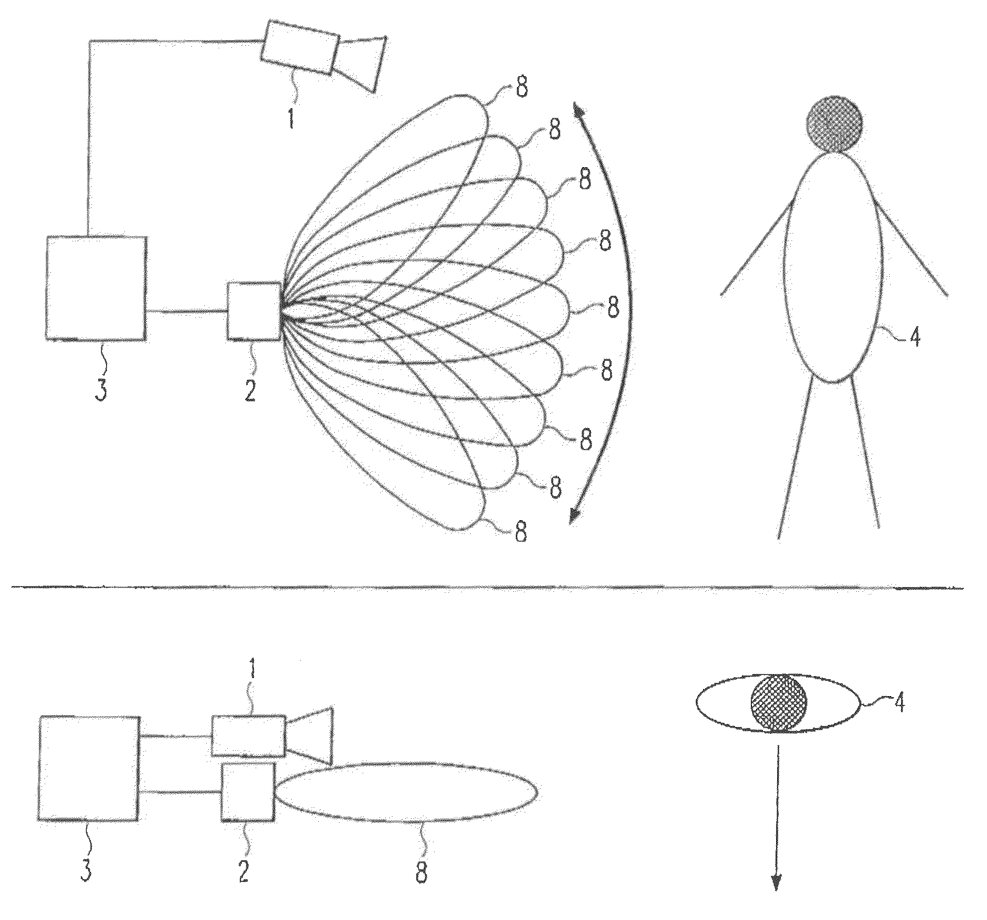
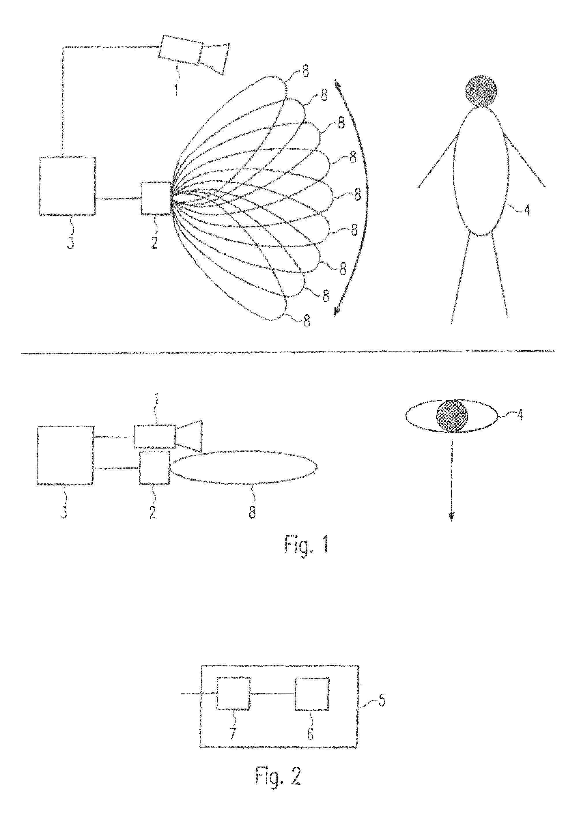
[0030]FIG. 1 shows a schematic front view and a schematic top view of the camera assisted sensor imaging system according to the present invention. The imaging system comprises a camera 1, a sensor unit 2 and a processing and control unit 3. The system may, for example, be a surveillance system used for performing a security screening in order to detect contraband objects. Other applications are possible however.

[0031]The camera 1 generates image information of a region of observation. The camera image information generated is of video type (‘video’ is used in the sense opposing ‘still image’). The camera 1 may be an optical or an infrared (IR) camera or may operate in both wavelength ranges.

[0032]The processing and control unit 3 provides an image recognition and tracking capability and may be implemented in hardware and / or software. Based on the camera image information, the processing and control unit 3 detects targets 4. Targets 4 may be human beings, animals and non living obje...

second embodiment

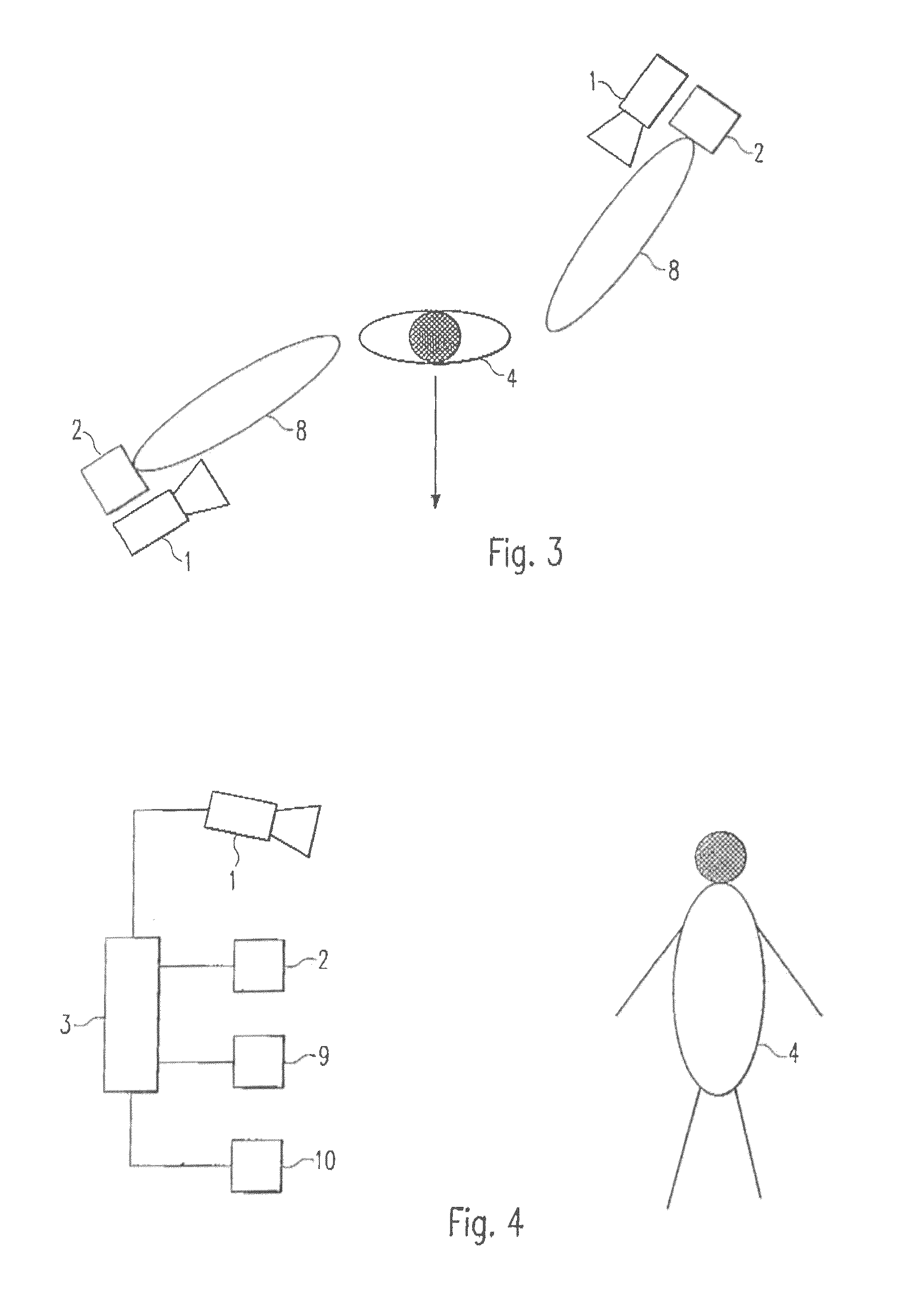
[0040]the camera assisted sensor imaging system according to the present invention will now be explained in which the imaging system is adapted to generate a two dimensional image of the target without the requirement that the target 4 is moving. Nevertheless, the target 4 may be allowed to move. FIG. 4 shows a schematic representation of the embodiment.

[0041]The camera assisted sensor imaging system of the second embodiment comprises a camera 1 as described above and a processing and control unit 3 adapted to evaluate the camera image data as described above. The system further comprises a sensor unit 2 operable in the microwave, millimeter wave and / or Terahertz frequency range. The sensor unit 2 of the second embodiment provides additional functionality to the functionality of the sensor unit 2 of the first embodiment described above, since the sensor unit 2 of the second embodiment is adapted to scan a two dimensional field of view. The two dimensional field of view may be provid...


PUM


Abstract

The present invention relates to the fields of imaging systems, security screenings, contraband object detection, microwave screening, millimeter wave screening and Terahertz screening. The present invention especially relates to a camera assisted sensor imaging system and a multi aspect imaging system.The camera assisted sensor imaging system according to the present invention comprises an optical and / or infrared camera unit for generating camera image information, a processing and control unit for detecting targets based on the generated camera image information, and a sensor unit adapted to successively scan portions of a detected target and to generate a plurality of corresponding image information parts, whereby the sensor unit is operable in the microwave, millimeter wave and / or Terahertz frequency range, and the processing and control unit is further adapted to construct an image of the target based on the image information parts and based on the generated camera image information.The multi aspect imaging system according to the present invention comprises one or more reflective elements and a sensor section operable in the microwave, millimeter wave and / or Terahertz frequency range. The sensor section is adapted to scan a first and a second aspect of a target, whereby the second aspect is scanned via a reflective element and the second aspect is scanned directly or via another reflective element.

Description

FIELD OF THE PRESENT INVENTION[0001]The present invention relates to the fields of radiometric imaging systems, security screenings, contraband object detection, microwave screening, millimeter wave screening and Terahertz screening. The present invention especially relates to a camera assisted sensor imaging system and a multi aspect imaging system operable in the microwave, millimeter wave and / or Terahertz frequency range.DESCRIPTION OF THE PRIOR ART[0002]Sensor imaging systems are known to be applied in a wide range of applications including for example medical, industrial (e.g. quality control) and security / surveillance related applications.[0003]The type of sensors employed for sensing an image depends upon the application. Examples of sensors include microwave sensors and x-ray sensors. The wavelengths ranging from of 1000 mm to 1 mm are commonly referred to as microwaves. Other definitions cite 300 mm for the upper bound of the microwave spectrum and 10 mm for the lower bound...

Claims


Application Information

Patent Timeline
Patent Type & Authority Patents(United States)
IPC IPC(8): H04N5/33G01S17/89
CPCG01S7/4802G01S13/50G01S13/887G01S13/89G01S17/89H04N5/225G01S13/867G01V8/005H04N23/00
Inventor KOCH, STEFANGUTHOERL, MARC
Owner SONY CORP
Why Eureka
Try Eureka