Supercharge Your Innovation With Domain-Expert AI Agents!

Low-energy optical detonator

a low-energy optical and detonator technology, applied in the direction of blasting cartridges, ammunition fuzes, weapons components, etc., can solve the problem of difficult ignition of such a large volume of combustion, and achieve the effect of reliable and high-efficiency ignition devices

Inactive Publication Date: 2006-05-30
INSTITUT FRANCO ALLEMAND DE RES & DEVS DE SAINT LOUIS
View PDF25 Cites 8 Cited by
  • Summary
  • Abstract
  • Description
  • Claims
  • Application Information

AI Technical Summary

Benefits of technology

The use of pyrotechnics significantly enhances the reliability and speed of detonator ignition, reducing the time required to trigger the detonator by a factor of 5 to 10 compared to optically doped detonators, while maintaining stability under extreme conditions.

Problems solved by technology

The problem posed is that of making a low-energy optical detonator in which the effectiveness of the ignition device is reliable and high, particularly when such a detonator is for use in severe environments.
Propulsive powders are generally used in large quantities, a 120 mm cannon uses about 8 kilograms (kg) of propulsive powder in a 10 liter (l) chamber—and igniting the combustion of such a large volume is difficult, making it necessary to use an ignitor squib containing an pyrotechnics.

Method used


Image

  • Low-energy optical detonator
  • Low-energy optical detonator

Examples


Embodiment Construction

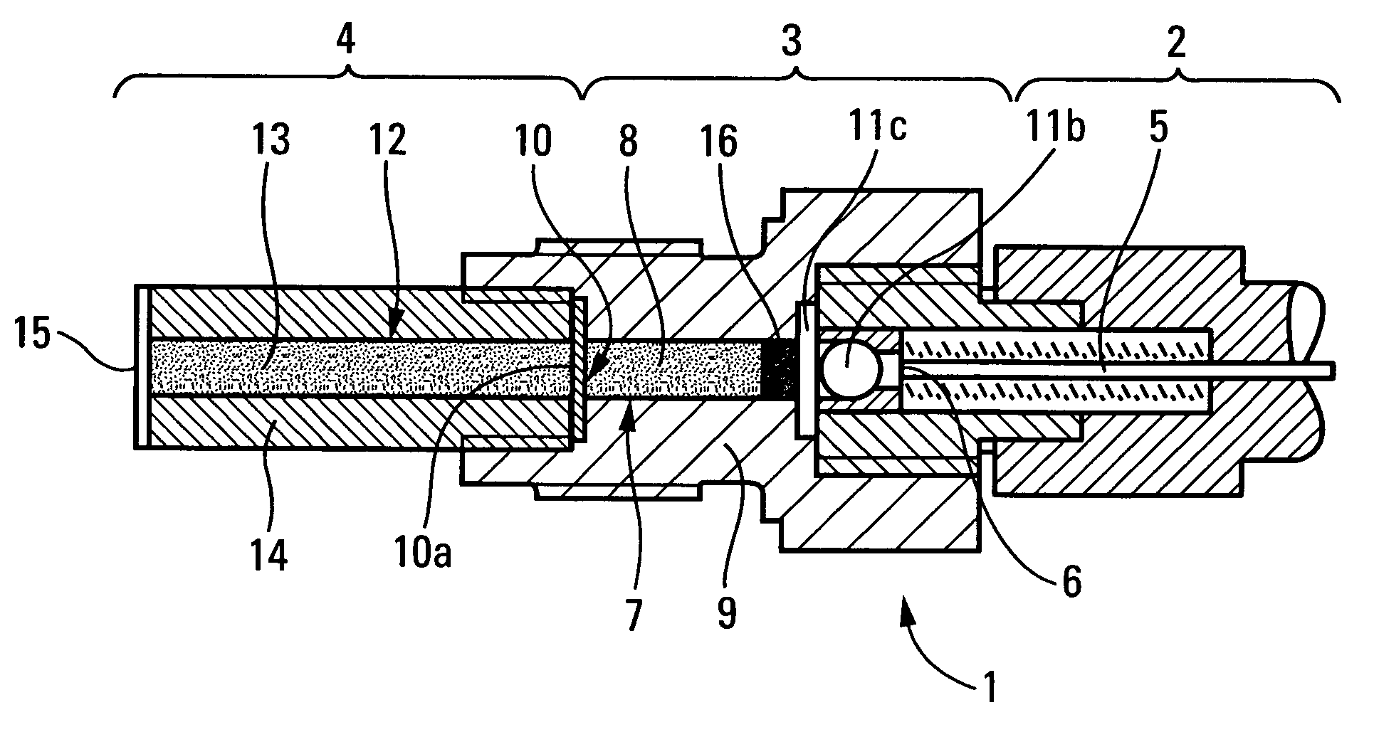
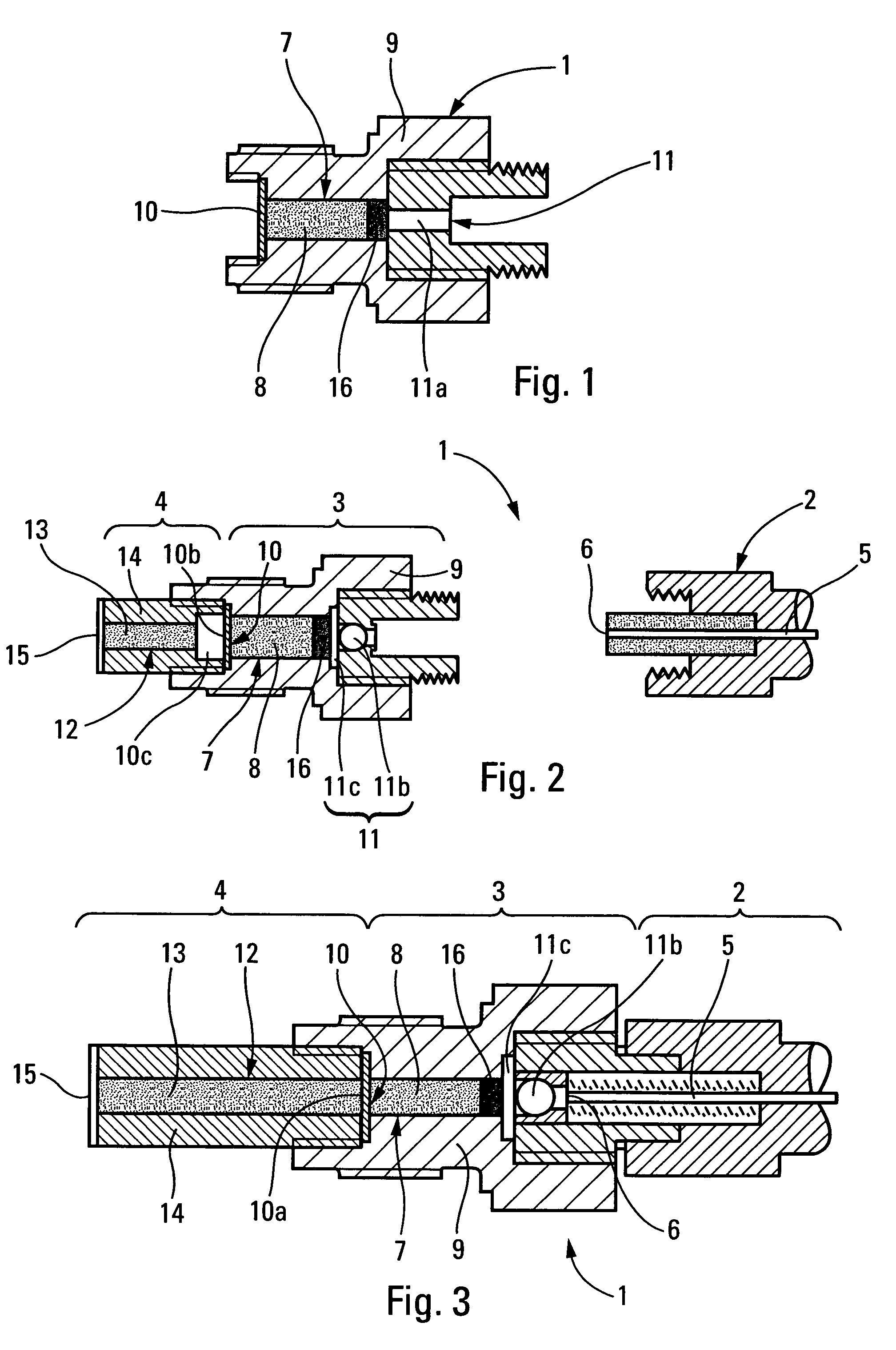
[0028]As can be seen in the accompanying figures, the optical detonator 1 comprises an endpiece 2, a first stage 3, and a second stage 4.

[0029]The endpiece 2 serves as a support for an optical fiber 5 having a first end connected to a laser source and having its second end 6 free.

[0030]The first stage 3 comprises a housing 7 having confined therein a deflagrating secondary explosive 8. Confinement is achieved by the walls of the structure 9 of the first stage 3, a device 10 serving to trigger transition to detonation in the second stage 4 at a first end, and a focusing optical interface 11 at the other end.

[0031]Once the endpiece 2 has been secured to the first stage 3 of the detonator 1, the second end 6 of the optical fiber 5 is in the immediate vicinity of the focusing optical interface 11, said interface 11 serving to separate the housing 7 from the optical fiber 5.

[0032]The second stage 4 has a housing 12 with a detonating secondary explosive 13 confined therein. This confineme...


PUM


Abstract

The invention relates to an optical detonator comprising a secondary explosive disposed in a cavity, an optical fiber having one end connected to a source of laser radiation, and a focusing optical interface situated between the other end of the optical fiber and the secondary explosive and adapted to transmit the laser radiation to the secondary explosive. According to the invention, a layer of an ignition powder is disposed in the cavity between the secondary explosive and the focusing optical interface.

Description

[0001]The present invention relates to low-energy optical detonators in which initiation is performed by a laser source which may be constituted, for example, by a laser diode.BACKGROUND OF THE INVENTION[0002]A detonator is a device designed to initiate detonation of an external charge of secondary explosive situated downstream therefrom; in order to do that, every detonator contains a small quantity of secondary explosive (100 milligrams (mg) to 1 gram (g)) which needs to be brought to detonation (at least) in its terminal portion starting with energy supplied to the inlet of the detonator from an external source.[0003]In known manner, an optical detonator is a detonator of the type comprising secondary explosive disposed in a cavity, an optical fiber connected at a first end to a source of laser radiation, and a focusing optical interface situated between the other end of the optical fiber and the secondary explosive, and adapted to transmit the laser radiation to the secondary ex...

Claims


Application Information

Patent Timeline
Patent Type & Authority Patents(United States)
IPC IPC(8): F42C19/00F42B3/113
CPCF42B3/113
Inventor MOULARD, HENRYRITTER, AUGUSTREBRODBECK, JEAN-MARIE
Owner INSTITUT FRANCO ALLEMAND DE RES & DEVS DE SAINT LOUIS
Features
  • R&D
  • Intellectual Property
  • Life Sciences
  • Materials
  • Tech Scout
  • Unparalleled Data Quality
  • Higher Quality Content
  • 60% Fewer Hallucinations
Learn More