Blowby gas circulation system and the method of circulation

a circulation system and blowby gas technology, applied in the direction of combustion engines, casings, machines/engines, etc., can solve the problems of bringing the adverse effect of the separation of gas from liquid to the air cleaner, and the ineffective operation of the separation of gas from liquid

Inactive Publication Date: 2006-05-30
SUBARU CORP
View PDF13 Cites 13 Cited by
  • Summary
  • Abstract
  • Description
  • Claims
  • Application Information

AI Technical Summary

Benefits of technology

[0006]It is an object of the present invention to provide an engine in which gas and liquid are effectively separated from a gas-liquid mixture generated in the crankcase and engine oil is prevented from flowing out to an intake system of the engine.

Problems solved by technology

However, according to the aforesaid prior art, since the greater part of the liquid and gas mixture in the crankcase is guided directly to the breather chamber, in case where the amount of the liquid and gas mixture exceeds a capacity of separating gas from liquid, the separation of gas from liquid can not be effectively performed.
As a result, the liquid and gas mixture blows out from the breather chamber and engine oil flows out to the intake system and an adverse effect is brought to an air cleaner and the like.

Method used


Image

  • Blowby gas circulation system and the method of circulation
  • Blowby gas circulation system and the method of circulation
  • Blowby gas circulation system and the method of circulation

Examples


Embodiment Construction

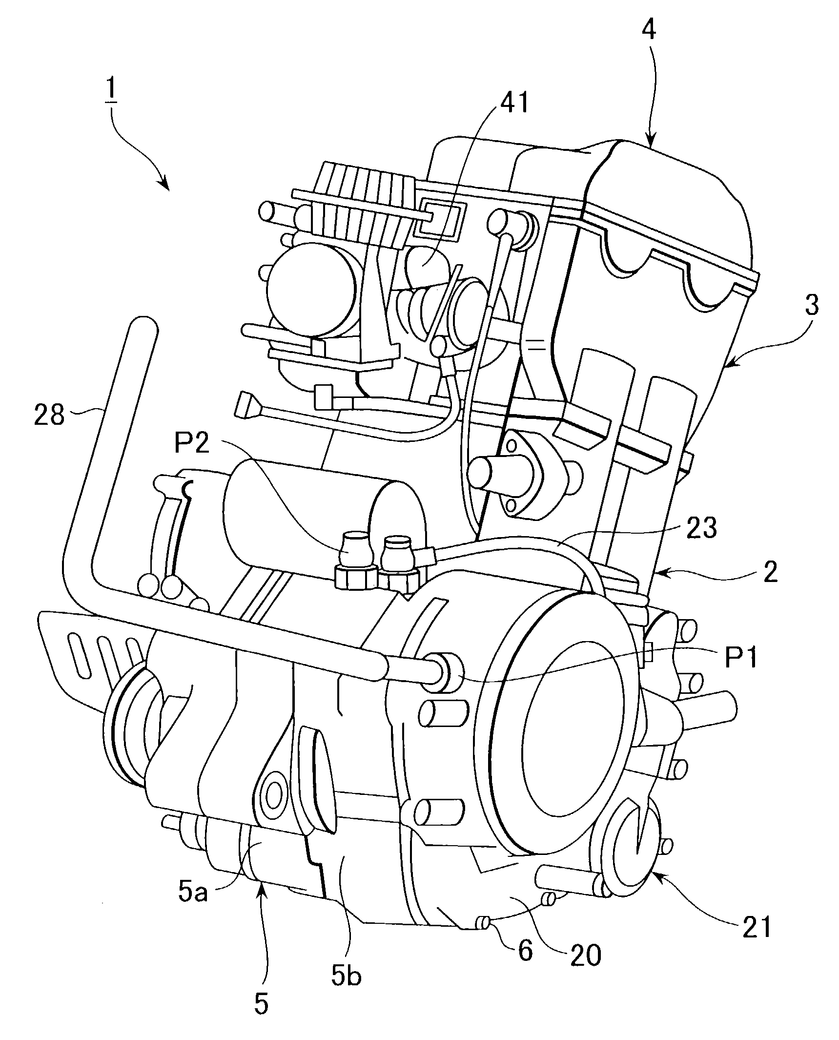
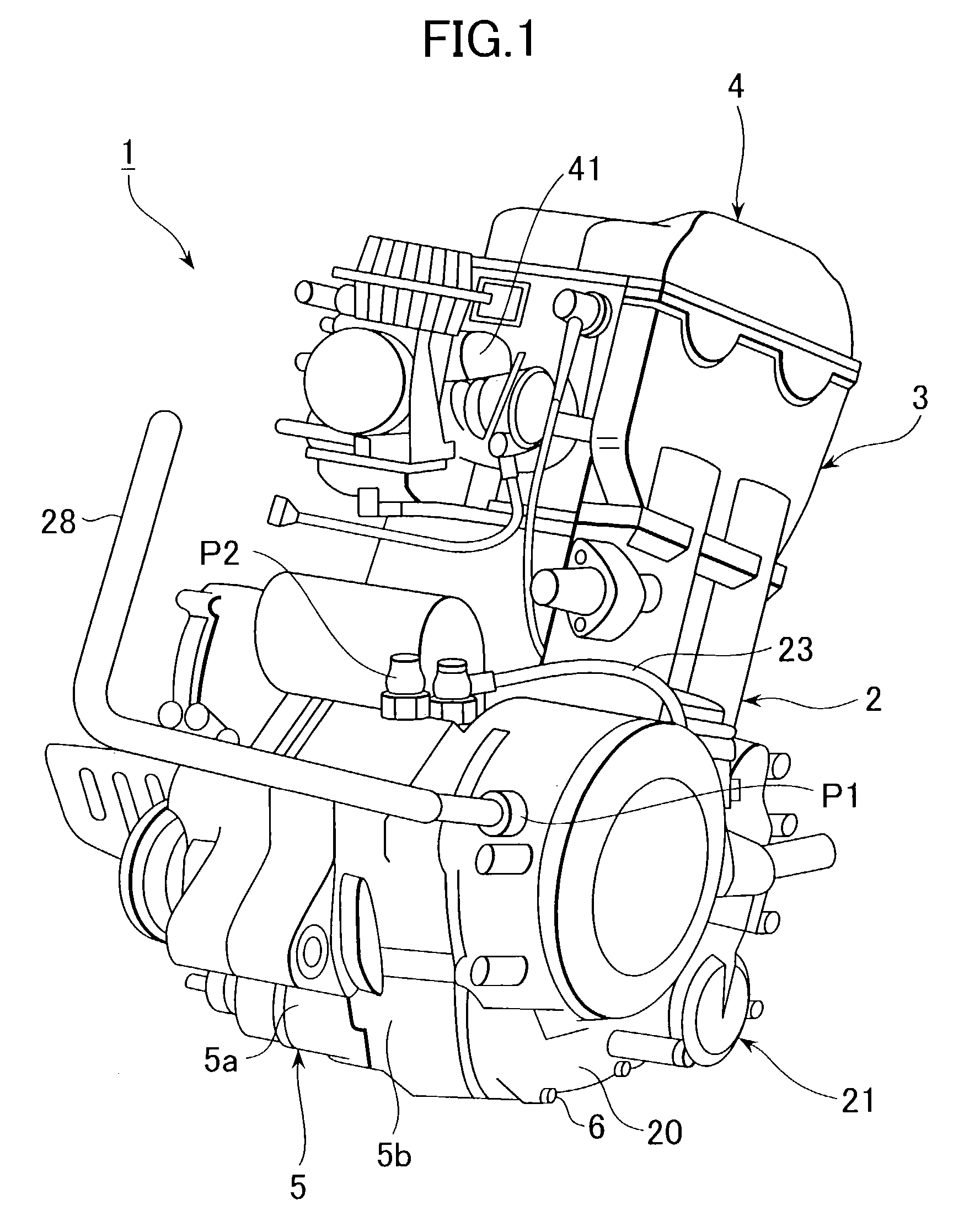
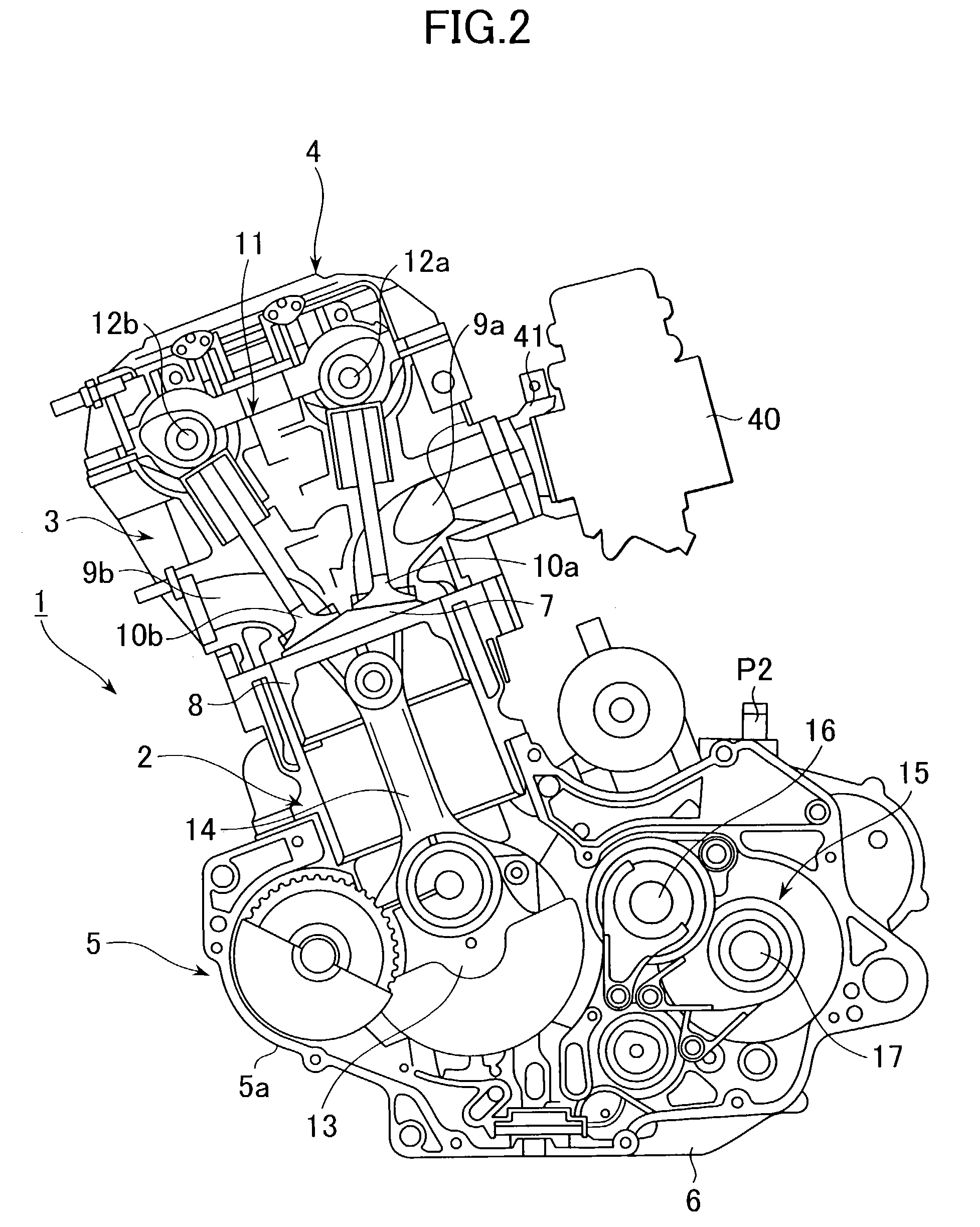
[0016]Referring now to FIGS. 1, 2 and 3, an engine 1 is mainly constituted by a cylinder case 2, a cylinder head 3, a cylinder head cover 4, a crankcase 5 and an oil pan 6. The cylinder head 3 has a combustion chamber 7 and the cylinder case 2 has a cylinder in which a piston 8 is reciprocatably accommodated. The cylinder head 3 has an intake and exhaust ports 9a, 9b and an intake and exhaust valves 10a, 10b for opening and closing the intake and exhaust ports 9a, 9b, respectively. The intake and exhaust valves 10a, 10b are driven by two camshafts 12a, 12b constituting a part of a cam mechanism 11, respectively. The crankcase 5 is formed by integrally connecting a first crankcase 5a with a second crankcase 5b. A crankshaft 13 supported by the crankcase 5 is connected with a connecting rod 14 for transforming a reciprocating motion of the piston 8 into a rotational motion and transferring the rotational motion to the crankshaft 13.

[0017]The first crankcase 5a incorporates a transmiss...


PUM


Abstract

A blowby gas circulation system for an engine having a crankcase and an intake system includes an oil tank which is independent of the crankcase, a first breather chamber and second breather chamber which are integrally provided with the crankcase. The oil tank supplies engine oil reserved therein to the crankcase and introduces a first gas-liquid mixture generated in the crankcase. The first gas-liquid mixture is separated into a second gas-liquid mixture and engine oil in the oil tank. Then, the second gas-liquid mixture is sent to a first breather chamber, being separated into a third gas-liquid mixture and engine oil. The third gas-liquid mixture is sent to a second breather chamber in which the third gas-liquid mixture is separated into blowby gas and engine oil. The blowby gas is sucked into the intake system and the engine oil is returned to the crankcase.

Description

BACKGROUND OF THE INVENTION[0001]1. Field of the Invention[0002]The present invention relates to a blowby gas circulation system for a drysump lubrication type engine and a method of circulating blowby gas.[0003]2. Discussion of Background Arts[0004]Japanese Patent Application Laid-open No. Toku-Kai-Hei 11-148333 discloses a technology of a blowby gas circulation system for a drysump lubrication type engine. Specifically, in the blowby gas circulation system, a mixture of liquid (engine oil) and gas (blowby gas generated in a crankcase) is introduced to a breather chamber and the separation of gas from liquid is performed therein. The separated blowby gas is introduced to an intake system of the engine and the separated oil is returned to the crankcase. Further, the liquid and gas mixture in an oil tank is introduced to the breather chamber and the aforesaid separation of gas from liquid is performed.[0005]However, according to the aforesaid prior art, since the greater part of the ...

Claims


Application Information

Patent Timeline
Patent Type & Authority Patents(United States)
IPC IPC(8): F01M13/00F01M1/02F01M11/00F01M13/02F01M13/04F02F7/00
CPCF01M13/021F01M2013/0461
Inventor TOMITA, KAZUSHIKANEKO, YASUHIRO
Owner SUBARU CORP
Why Eureka
Try Eureka