Closure for a pressure vessel and method

a technology for sealing and pressure vessels, applied in the field of sealing, can solve the problems of difficulty in manufacturing and operating, inability to incorporate an integral safety locking feature, and inability to manufacture and operate prior art designs, etc., and achieve the effect of easy opening and closing, high reliability

Inactive Publication Date: 2006-05-30
ROBBINS & MYERS ENERGY SYST +1
View PDF29 Cites 26 Cited by
  • Summary
  • Abstract
  • Description
  • Claims
  • Application Information

AI Technical Summary

Benefits of technology

[0016]An advantage of the present invention is that the closure is highly reliable, and the door may be easily opened and closed.

Problems solved by technology

Many of these prior art designs are similar in concept, but are complex, difficult to manufacture and operate, and / or require removal of material from critical pressure retaining surfaces that prevent compliance with international design codes.
In-addition, these prior art designs do not and some practically cannot incorporate an integral safety locking feature that prevents unsafe handling and operation of the closure.
European Patent Specification 0129349 discloses a closure which does include a safety locking feature, although the closure does not overcome many of the other deficiencies with prior art closures.

Method used


Image

  • Closure for a pressure vessel and method
  • Closure for a pressure vessel and method
  • Closure for a pressure vessel and method

Examples


Embodiment Construction

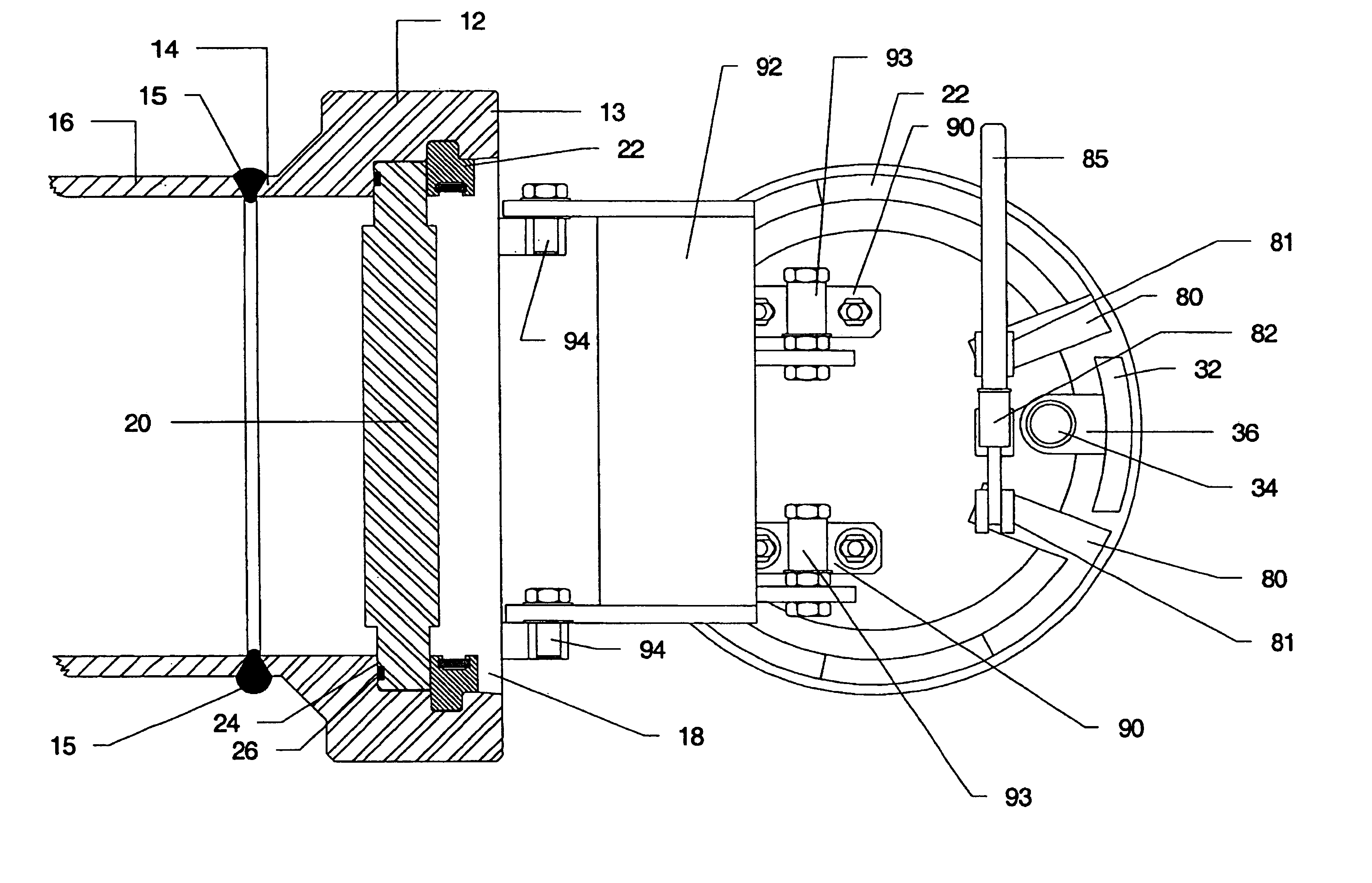
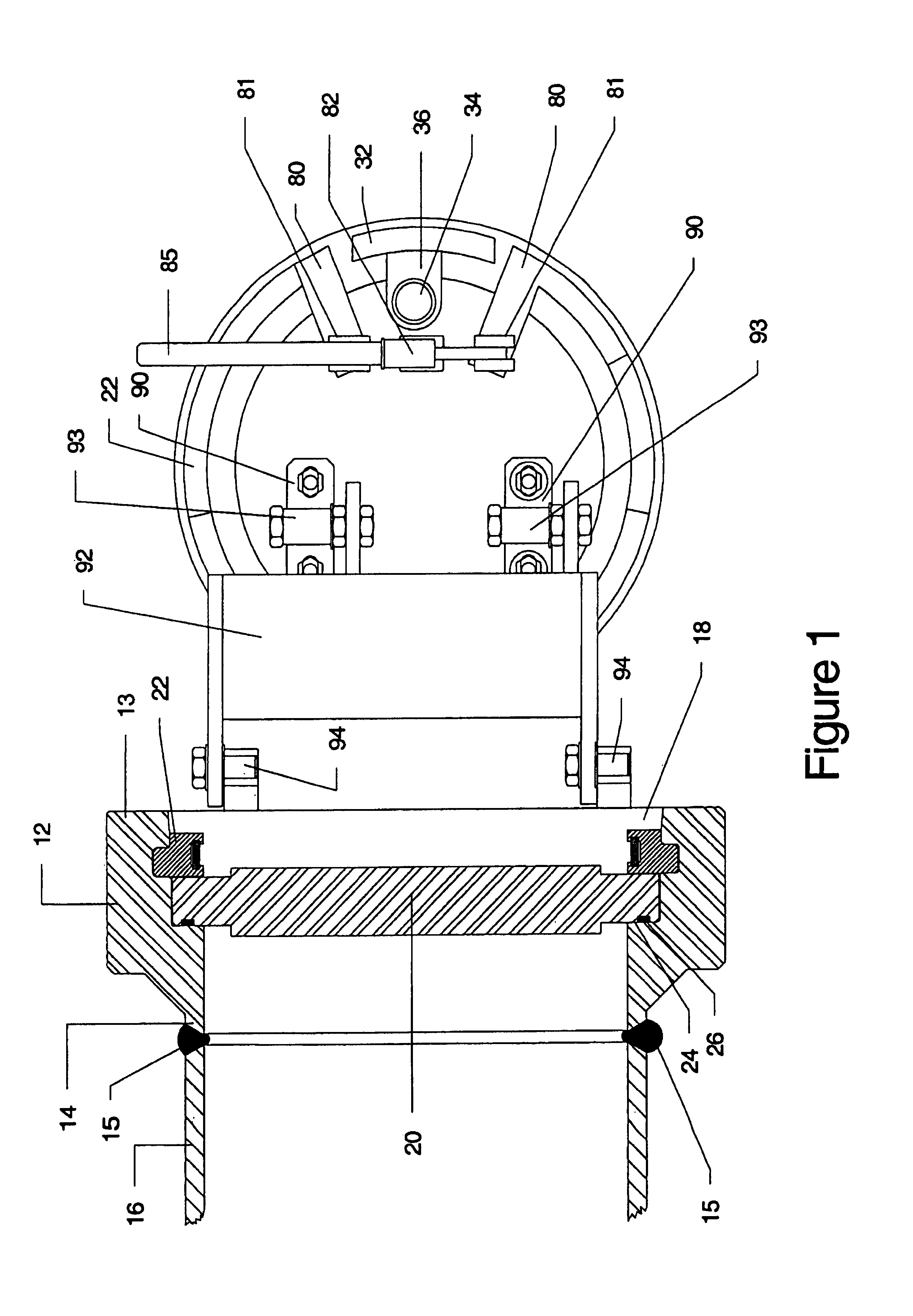
[0035]A closure assembly 10 is provided for retaining positive and / or vacuum pressures within a pressure vessel 16, typically by a weld 15. A neck 12 having a beveled free end 13 and an attachment end 14 is secured to a pipeline, tank, or other pressure vessel 16, typically by a weld 15. In a preferred embodiment, the neck 12 includes an internal profile 18 for receiving an actuated locking member 22 and a door 20, as shown in FIG. 3. An internal profiled ledge 24 within the closure neck 12 provides a sealing surface against which an elastomeric seal 26 is pressed to form a pressure retaining boundary. A reliable seal across the pressure differential between vessel pressure and atmosphere may be achieved by a hand applied force, or with a fluid powered actuator, as explained below. FIG. 1 shows the position at the locking member 22 in dashed lines when the door 20 is closed and the locking member 22 is in the closed position.

[0036]Locking member 22 is radially expandable and contrac...


PUM


Abstract

A closure assembly 10 contains positive and / or vacuum pressure within a pressure vessel 16 having a neck 12. A circumferential locking member 22 supported on a door 20 locks the door to the neck, and is radially moveable between an open position and a closed position. A seal 26 between the neck and the door maintains fluid-tight integrity. A lever or other hand powered operator may be used for moving the locking member between the open position and the closed position. The locking member may include locking segments interconnected to form the circumferential locking member.

Description

RELATED APPLICATION[0001]The application is a Continuation-In-Part of U.S. Design Application 29 / 150,087, filed 05 Nov. 2001 now abandoned.FIELD OF THE INVENTION[0002]The present invention relates to closures of the type used for sealing the end of a pressure vessel, such as a pipe. More particularly, the present invention relates to an improved closure for reliably sealing either positive pressure or a partial vacuum within the vessel, while allowing easy access to the pressure vessel by opening the door.BACKGROUND OF THE INVENTION[0003]Various designs of quick acting closures (clamp type, clutch type, screw type and bridge type) have been utilized on pressure vessels, including pipelines, within the chemical, oil and gas, food, and nuclear industries. The demand to frequently obtain access to pressure vessels has been increasing, thereby enhancing the need for a safe closure that provides quick opening and closing / sealing capabilities.[0004]Examples of prior art closures are discl...

Claims


Application Information

Patent Timeline
Patent Type & Authority Patents(United States)
IPC IPC(8): F16J13/10B65D45/34F16J15/10B01J3/03B65D45/00B65D90/10F16J13/08F16K51/00F16L55/11F17C13/06
CPCB01J3/03F16J13/08F16J13/10F16J13/20F16K51/00F16L55/11F17C13/06B65D90/10F17C2270/05B65D2590/666G21F5/12F17C2201/0104F17C2201/056F17C2201/058F17C2205/0173F17C2205/0379F17C2209/221F17C2209/228F17C2225/033F17C2225/035F17C2225/036F17C2225/038F17C2250/043F17C2260/011Y10T292/216Y10T292/212Y10T292/34
Inventor MCGUIRE, DOUGLAS J.
Owner ROBBINS & MYERS ENERGY SYST
Why Eureka
Try Eureka