Dermabrasion apparatus and method having oval-shaped mixing bottle

Inactive Publication Date: 2006-05-30
MATTIOLI ENG
View PDF8 Cites 33 Cited by
  • Summary
  • Abstract
  • Description
  • Claims
  • Application Information

AI Technical Summary

Benefits of technology

[0010]According to yet another aspect of the invention, there is provided a method of dermabrading skin of a patient using a dermabrasion apparatus that includes a handpiece and a mixing container. The method includes attaching the handpiece

Problems solved by technology

A drawback of such systems is that the sterility of the various components is not guaranteed, without the use of complicated and expensive processes.
However, potential drawbacks of such an apparatus include the fact that the air pressurization is performed by a compressor placed inside the apparatus, making it necessary to sterilize the air because, during treatment, the compressor could be infected by bacteria which would be afterwards conveye

Method used


Image

  • Dermabrasion apparatus and method having oval-shaped mixing bottle
  • Dermabrasion apparatus and method having oval-shaped mixing bottle
  • Dermabrasion apparatus and method having oval-shaped mixing bottle

Examples


first embodiment

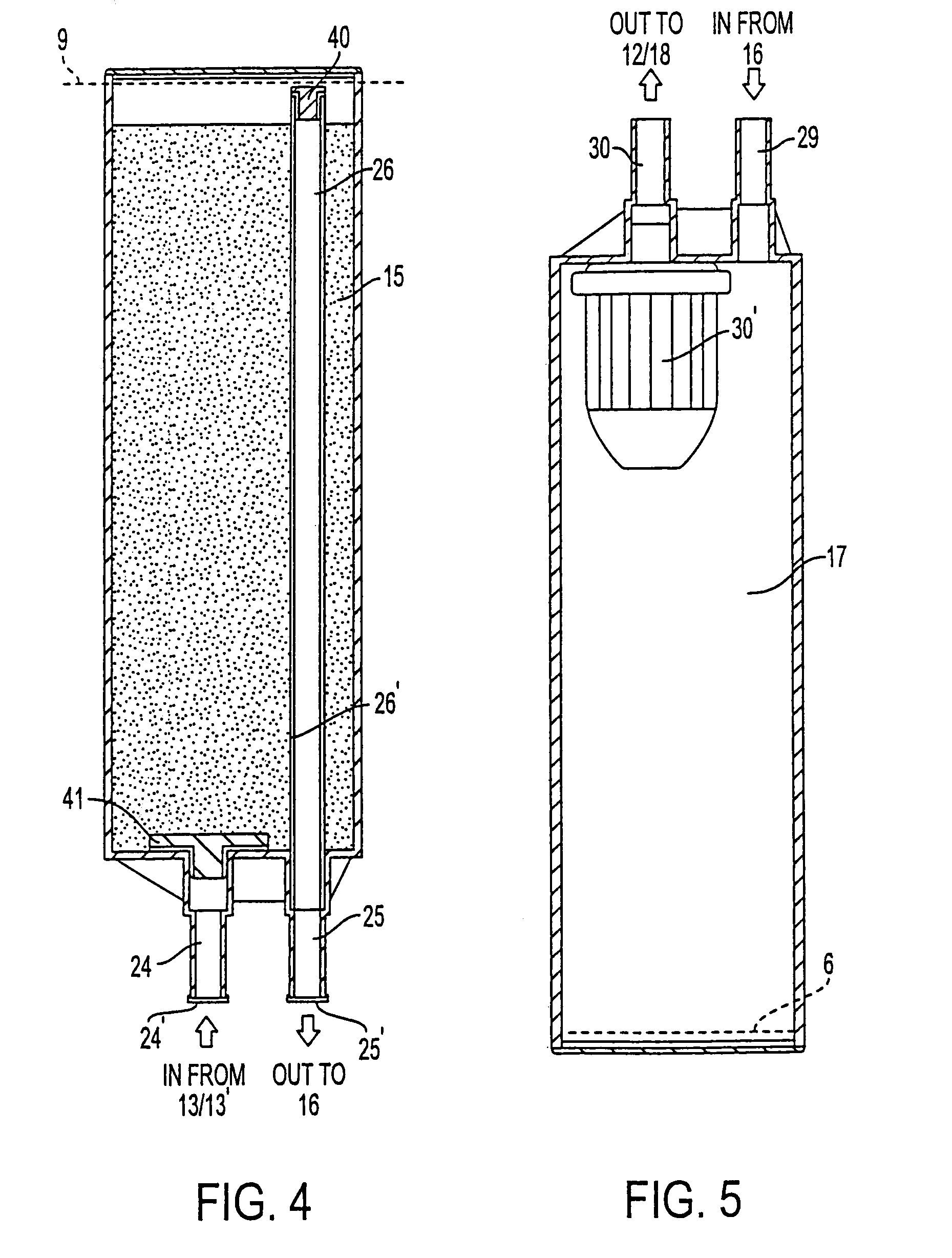
[0046]According to the invention, the mixing bottle 15 is filled with the corundum in an aseptic (sterilized) environment and thereafter is preferably by ultrasound welding, and then sealed by suitable plug 24′, 25′. In the one-piece, non-welded configuration, the corundum is placed into the mixing bottle, and then the mixing bottle is sealed by plugs 24′, 25′. For example, each plug 24′, 25′ can have a bottom rubber layer which is pierced by the extremities of corresponding connecting junctions of the external tray 23 when the plugs 24′, 25′ are fitted into the external tray 23. Alternatively, each plug 24′, 25′ may comprise an aluminum foil or strip, which is punctured when the mixing bottle 15 is fitted into the external tray 23. In such a way, the mixing bottle 15 is connected with the valve 13 and with the downstream handpiece 16.

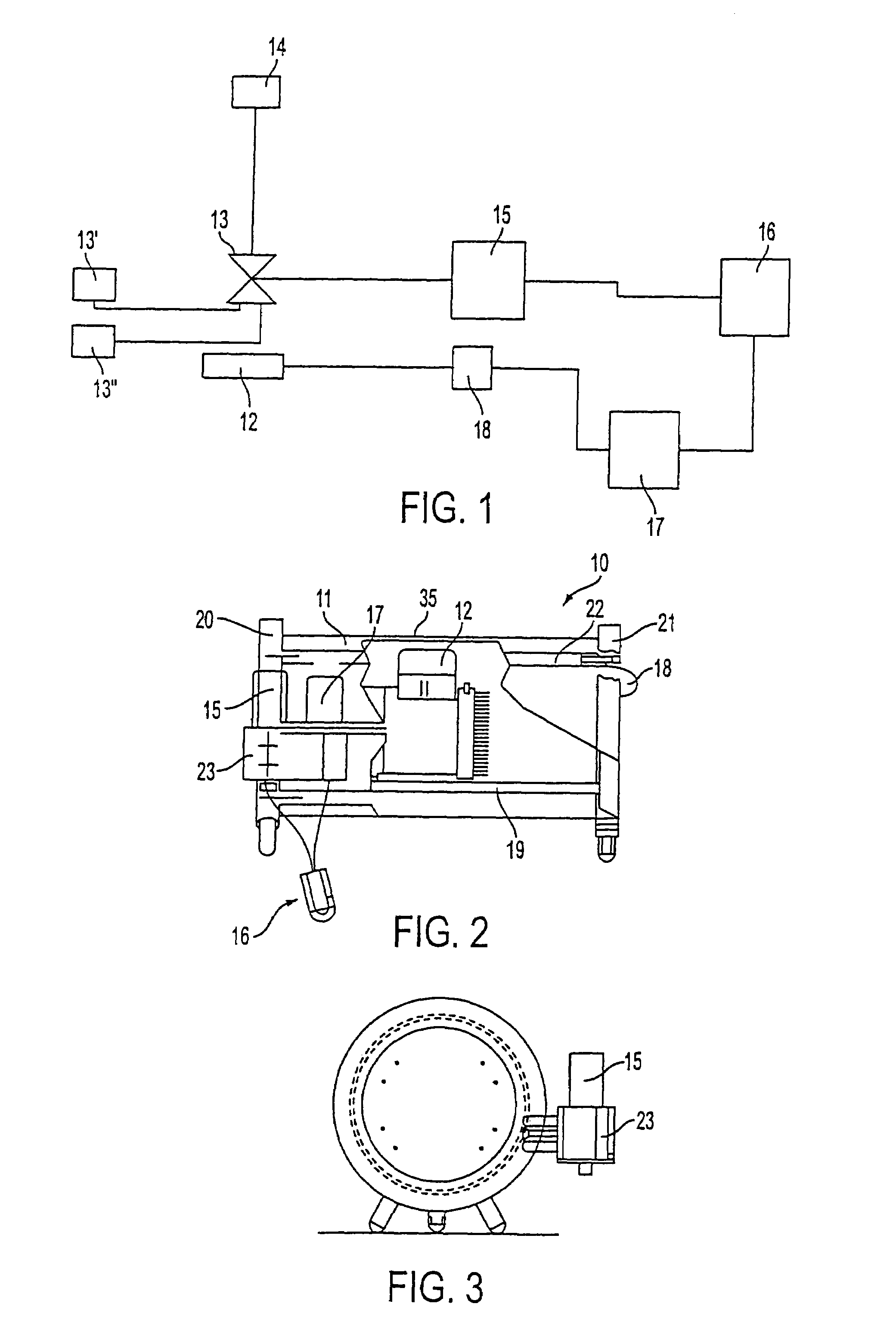
[0047]FIG. 10 shows the fitting of the mixing bottle 15 onto the external tray 23. In FIG. 10, the external tray 23 includes two connection pipes 50, ...

third embodiment

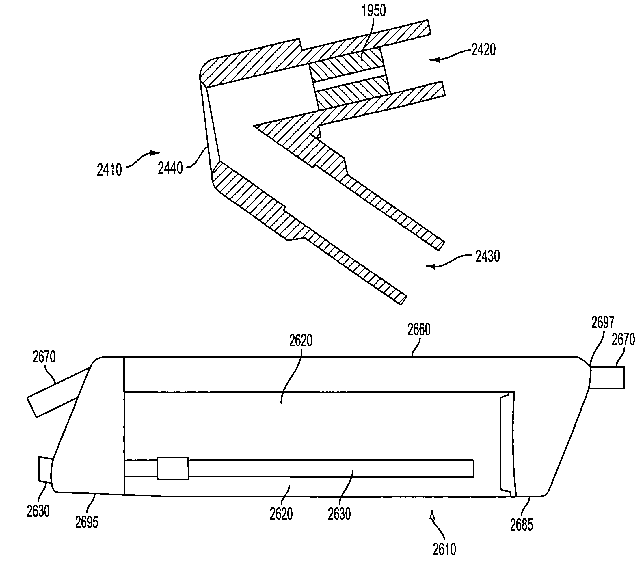
[0050]In a second configuration of the handle, as shown in FIG. 11, the contacting handpiece 16′ is a mono-block (single, non-separable unit) which includes an insert block 7′ situated in a curved portion at the top of the handpiece 16′. By this configuration, the air output from the insert block 7′ is directed towards the opening 34′, with the air direction being shown by the dashed line 88. The opening 34′ is positioned at a substantially central position of the handpiece 16′. A longitudinal axis of the handpiece 16′ that bisects the handpiece 16′ is shown by dashed line 92. In the second configuration of the handpiece, the handpiece 16′ is manufactured as a single piece (except of course the insert block 7′), without the need for combining sections to thereby form the handpiece. In a third embodiment, the insert block 7′ may be omitted, and instead the handpiece 16″ may be formed such that the location where the insert block 7′ is located in the second configuration is made narro...

second embodiment

[0062]FIG. 16 shows the present invention, which is a mono-block comprising a mixing bottle and a handle. The entire structure shown in FIG. 16 is a one-piece construction, and where the mixing bottle portion 15′ and the handle portion 16′″ together comprise the mono-block structure. In another possible configuration, the mixing bottle, the collecting bottle and the handle all together can be manufactured as a single, mono-block structure, to be disposed after treatment of a patient. As mentioned above, since there is no need to clean each component after treatment of a patient, as is required by conventional dermabrasion apparatuses, having a mono-block structure which combines more than one element (such as a mixing bottle and a handle; or a handle and a collecting bottle; or a handle, mixing bottle, and collecting bottle), the entire mono-block structure is disposed after treatment, and thus there is no need to connect individual components together as is required for conventiona...


PUM


Abstract

A dermabrasion apparatus operates by a flow of air and reducing substances conveyed to a patient through a handpiece. The apparatus includes an oval-shaped mixing bottle that has a first enclosed region for holding reducing substances. The mixing bottle includes a cap that has two tubes extending therefrom, for coupling to respective input and output legs of the handpiece. The mixing bottle also includes a second enclosed region for holding one of the two tubes that provides an air-tight coupling between the output leg of the handpiece and a collecting bottle. The mixing bottle is oval-shaped so that a user can readily manipulate the handpiece so as to move the handpiece coupled to the mixing bottle in a desired direction. This is especially useful for small handpieces that are hard to hold onto by themselves.

Description

RELATED APPLICATIONS[0001]The present application is a continuation-in-part of U.S. Ser. No. 09 / 302,423 filed Apr. 30, 1999, now U.S. Pat. No. 6,368,333, which itself is a continuation-in-part of U.S. Ser. No. 09 / 099,523 filed Jun. 18, 1998, now U.S. Pat. No. 6,306,147, which itself is a continuation-in-part of U.S. Ser. No. 08 / 496,470 filed Jun. 29, 1995, now U.S. Pat. No. 5,810,842, and U.S. Ser. No. 08 / 797,909 filed Feb. 10, 1997, now U.S. Pat. No. 6,120,512, all of which are incorporated in their entirety herein by reference.BACKGROUND OF THE INVENTION[0002]A. Field of the Invention[0003]The present invention relates to the field of the cosmetic and microsurgical treatments. In particular, the present invention relates to a microdermabrasion method and apparatus and to the components making up the apparatus, operating by a pressurized flow of air and reducing substances, preferably corundum.[0004]B. Description of the Related Art[0005]Several technical solutions to produce a mic...

Claims


Application Information

Patent Timeline
IPC IPC(8): A61B17/50A61B17/00A61B17/32A61B17/54A61M1/00
CPCA61B17/545A61B2017/00017A61B2017/0023A61B2217/007A61B2017/320004A61B2217/005A61B2017/00544
Inventor BERNABEI, GIAN FRANCO
Owner MATTIOLI ENG
Why Eureka
Try Eureka