
Semiconductor chip and fabrication method thereof

a semiconductor chip and semiconductor technology, applied in semiconductor devices, semiconductor/solid-state device details, electrical devices, etc., can solve the problems of affecting the formation of high-density semiconductor chips on semiconductor wafers

Active Publication Date: 2006-05-30
SHINKO ELECTRIC IND CO LTD
View PDF13 Cites 34 Cited by
  • Summary
  • Abstract
  • Description
  • Claims
  • Application Information

AI Technical Summary

Benefits of technology

[0008]It is a general object of the present invention to provide a novel and useful semiconductor chip and fabrication method thereof in which one or more of the above-mentioned problems are eliminated.
[0009]A more specific object of the present invention is to provide a method of fabricating a semiconductor chip that can shorten fabrication time and improve integration and yield of semiconductor chip formation.
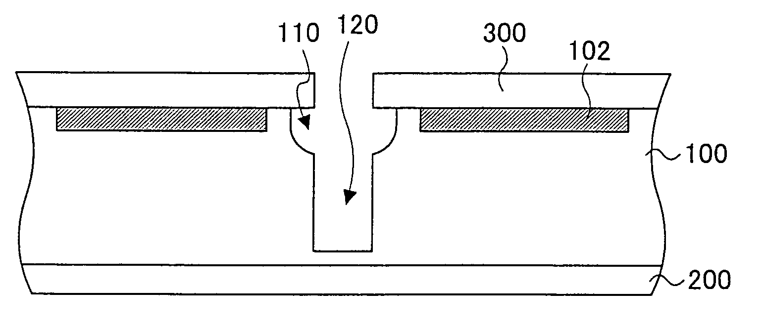
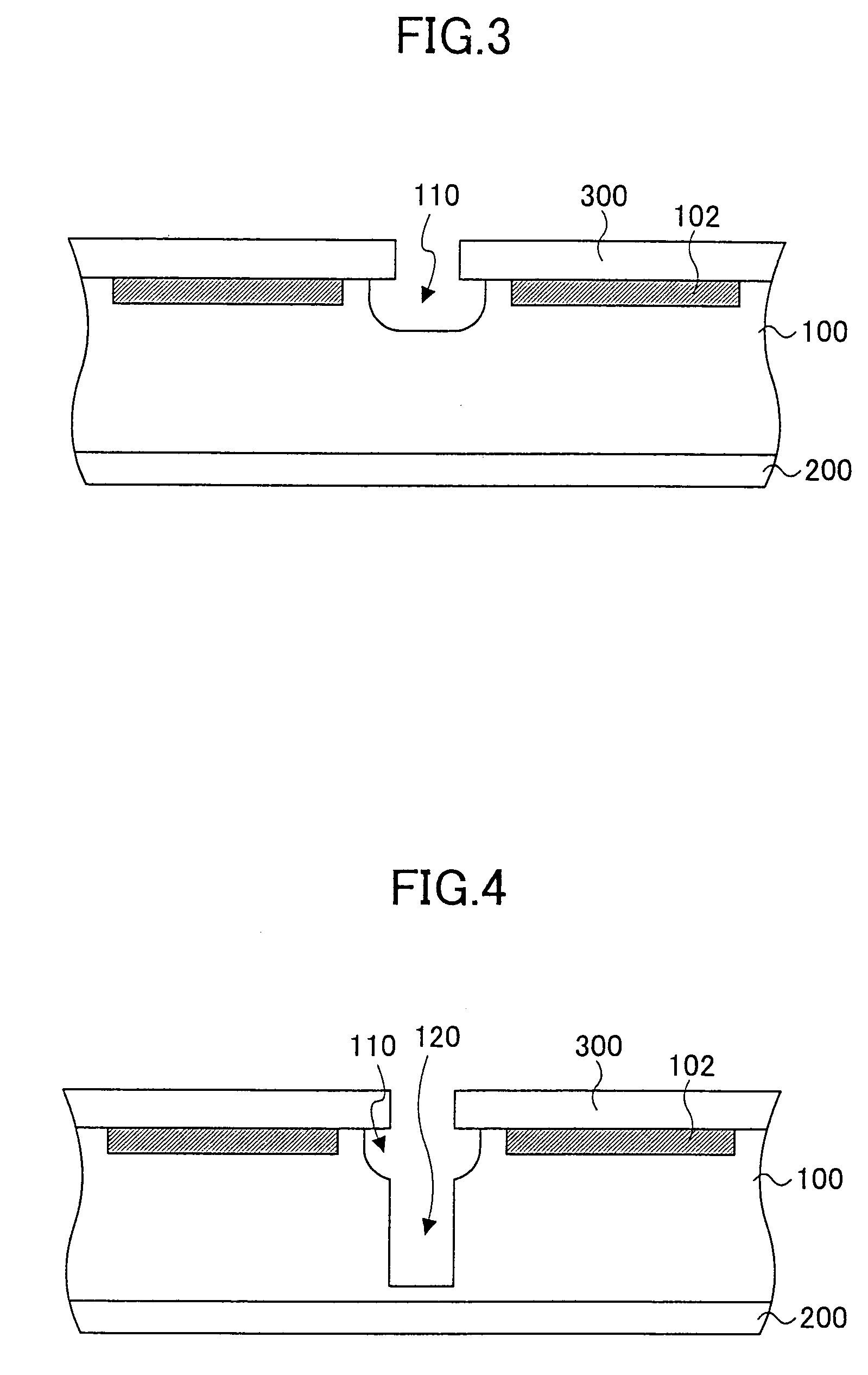
[0018]According to one aspect of the present invention, when a semiconductor wafer is diced, it is possible to etch the surfaces of the semiconductor wafer by performing isotropic etching and anisotropic etching. Accordingly, it is possible to shorten time required to fabricate semiconductor chips from the semiconductor wafer. In addition, since the semiconductor chip fabrication method according to the present invention does not need a dicing blade for dicing a semiconductor wafer, it is unnecessary to prepare a dicing line width corresponding to a dicing blade and reduce the dicing line width. As a result, it is possible to enhance integration of semiconductor chips on the semiconductor wafer, that is, it is possible to produce more semiconductor chips from the semiconductor wafer. In addition, since isotropic etching may be performed on a cutting portion from a first surface, on which at least one semiconductor element is formed, of a semiconductor wafer or a second surface opposite the first surface, it is possible to round off one or both edges of the first surface and the second surface. This configuration makes it possible to prevent chipping of the edge when the semiconductor chip is handled, and it is possible to improve yield of semiconductor chips.

Problems solved by technology

Thus, it takes more dicing time to produce more semiconductor chips.
In general, an interval between adjacent semiconductor chips has to be set as more than the dicing line width of about 50 μm, and this requirement adversely influences high-density semiconductor chip formation on a semiconductor wafer.
Such a thin semiconductor wafer is fragile to a dicing blade.
Such a box-shaped semiconductor chip has a significant problem in that a corner and an edge of the semiconductor chip may be chipped when the semiconductor chip is handled or carried, resulting in yield reduction thereof.

Method used


Image

  • Semiconductor chip and fabrication method thereof
  • Semiconductor chip and fabrication method thereof
  • Semiconductor chip and fabrication method thereof

Examples


Embodiment Construction

[0029]In the following, embodiments of the present invention will be described with reference to the accompanying drawings.

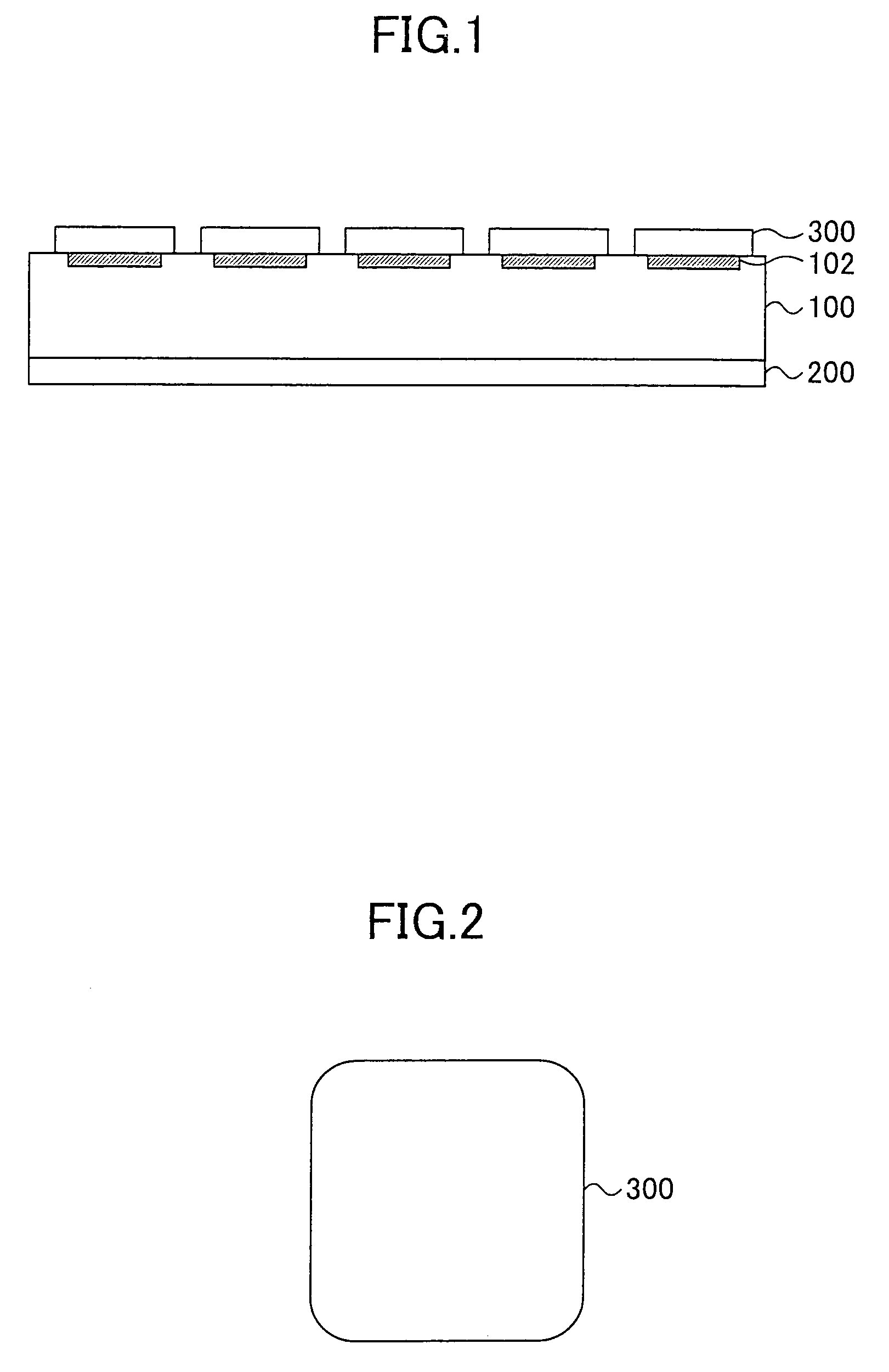
[0030]FIG. 1 shows a first fabrication process of a semiconductor chip according to an embodiment of the present invention. In the first fabrication process, a semiconductor chip fabrication apparatus fixes a semiconductor wafer 100, which is made of silicon and includes two surfaces: an element formation surface (upper side in FIG. 1) having a plurality of semiconductor elements 102 thereon and an element non-formation surface (lower side in FIG. 1) opposite to the element formation surface, by attaching the element non-formation surface of the semiconductor wafer 100 to a tape 200 as illustrated in FIG. 1.

[0031]In addition, the semiconductor chip fabrication apparatus provides a resist film on the element formation surface. Then, by exposing the resist film to light, the semiconductor chip fabrication apparatus removes the portion of the resist film on a cutti...


PUM


Abstract

A semiconductor chip and a fabrication method thereof are disclosed. In the fabrication method, isotropic etching and anisotropic etching are performed on a cutting portion of a semiconductor wafer to form grooves in the semiconductor wafer. Through these grooves, the semiconductor wafer can be diced with no use of any dicing blade. In addition, it is possible to form semiconductor chips whose edges and corners are rounded off. According to the fabrication method, fabrication time can be shorten. In addition, it is possible to improve integration and yield of semiconductor chip formation.

Description

BACKGROUND OF THE INVENTION[0001]1. Field of the Invention[0002]The present invention is related to a method of fabricating semiconductor chips by dicing a semiconductor wafer at a predetermined size.[0003]2. Description of the Related Art[0004]In a conventional semiconductor chip fabrication process, a semiconductor wafer, on which a plurality of semiconductor elements are formed, is diced in a dicing process of the fabrication process by shifting a rotationally-driven disk-shaped cutter (dicing blade) of a semiconductor chip fabrication apparatus vertically and horizontally so as to form a large number of semiconductor chips. In general, such semiconductor chips are box-shaped.[0005]In the above-mentioned conventional semiconductor chip fabrication process, since a dicing blade of a semiconductor chip fabrication apparatus is shifted vertically and horizontally to dice a semiconductor wafer, the semiconductor chip fabrication apparatus has to perform a greater number of cutting op...

Claims


Application Information

Patent Timeline
Patent Type & Authority Patents(United States)
IPC IPC(8): H01L21/46H01L21/301H01L21/78H01L21/302H01L21/52H01L21/304H01L21/461H01L21/50H01L23/34
CPCH01L21/78
Inventor KOIZUMI, NAOYUKI
Owner SHINKO ELECTRIC IND CO LTD
Learn More