Magnetron with a specific dimension reducing unnecessary radiation

a specific dimension and magnetic field technology, applied in the field of magnetic field, can solve the problems of deteriorating oscillation efficiency on the other side, difficult to completely clear the restrictions of unnecessary radiation using only the choke ring, and inability to improve oscillation efficiency, so as to achieve the effect of stabilizing the dark current characteristi

Active Publication Date: 2006-05-30
PANASONIC CORP
View PDF5 Cites 3 Cited by
  • Summary
  • Abstract
  • Description
  • Claims
  • Application Information

AI Technical Summary

Benefits of technology

[0022]The present invention has been made to solve the above-mentioned problems in consideration with the above knowledge, and it is an object of the present invention to provide a magnetron capable of sufficiently reducing unnecessary radiation and of improving oscillation efficiency.
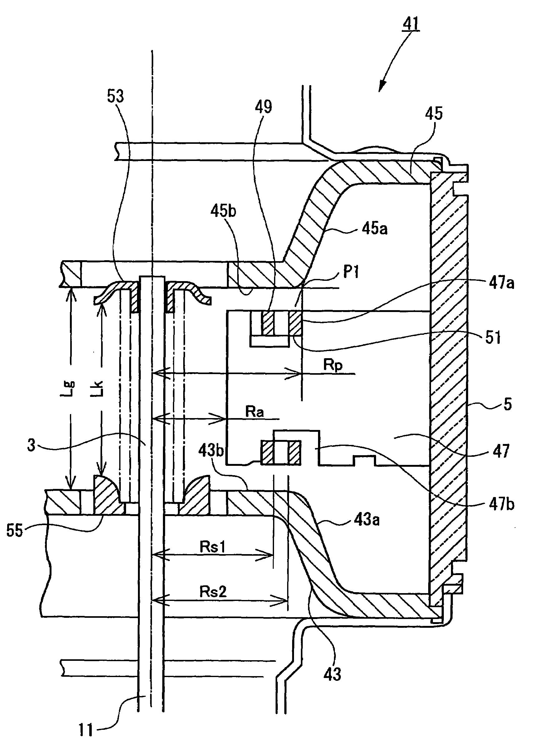
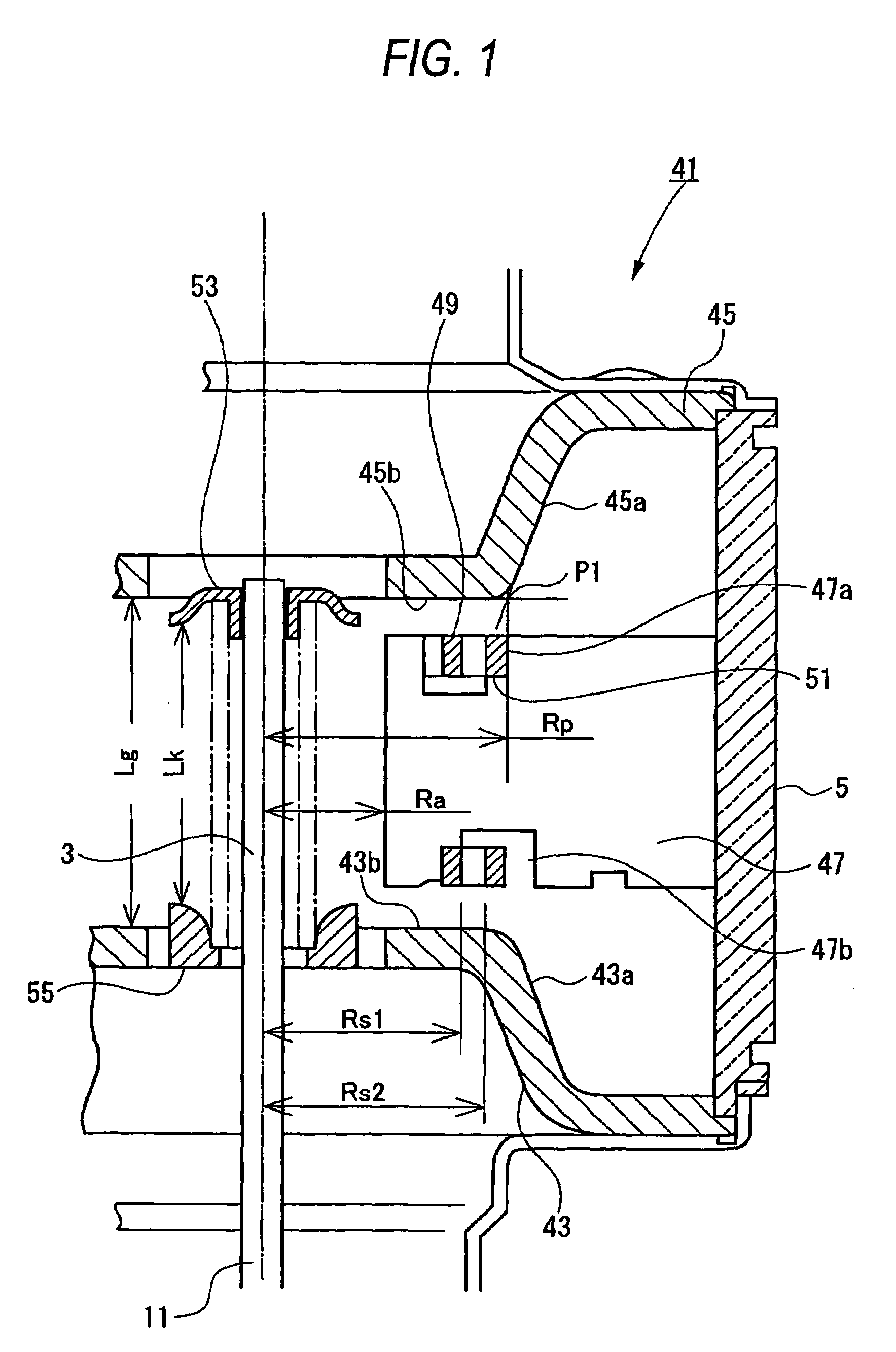
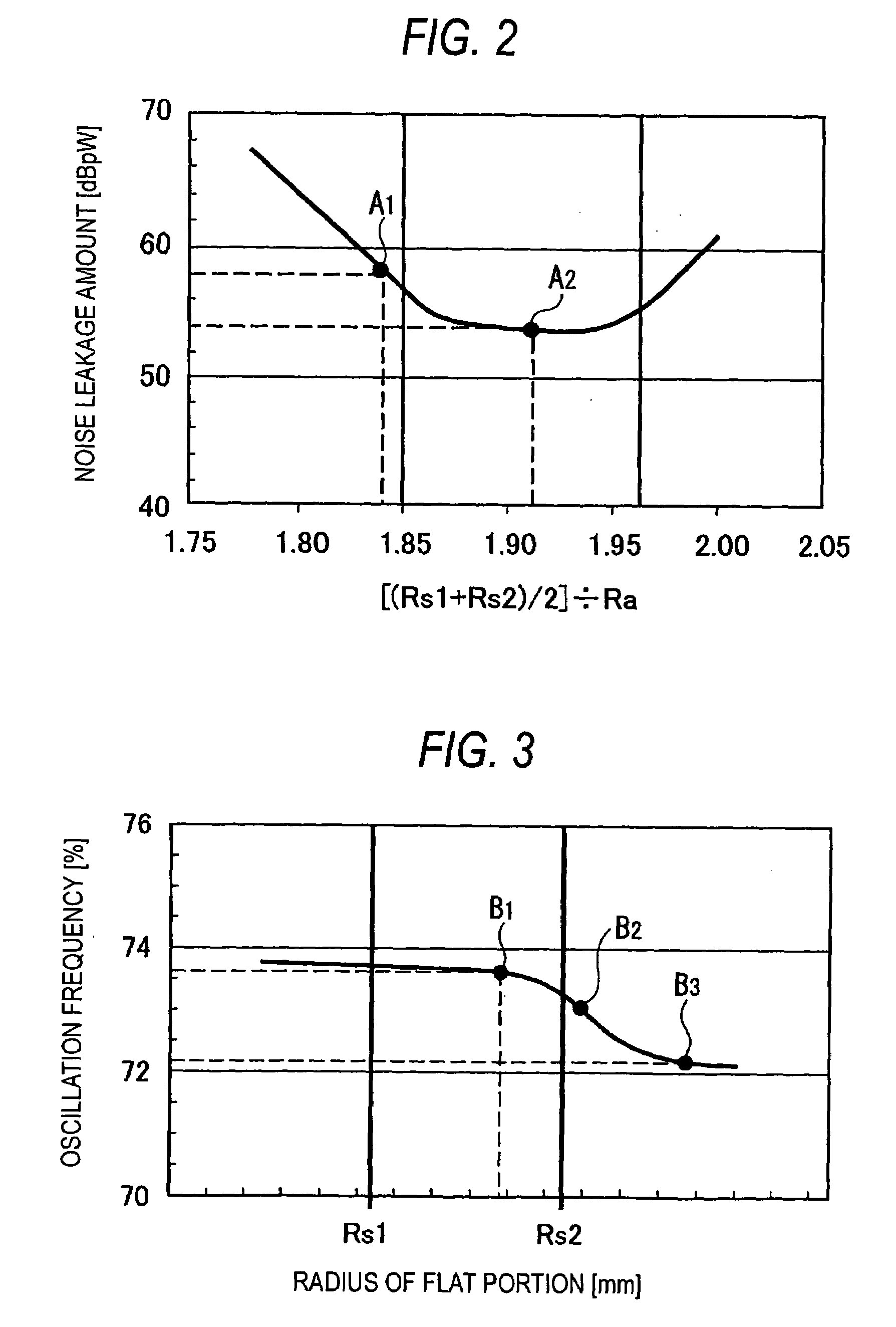
[0025]For example, the noise leakage amount of the fifth harmonic wave has a downwardly convex curve characteristic where the leakage amount is minimum in the vicinity of [(Rs1+Rs2 / 2)]÷Ra=1.90. Therefore, the values of Rs1, Rs2, and Ra are set such that [(Rs1+Rs2 / 2)]÷Ra is included within the proper range in the vicinity of the minimum value, and thus it is possible to minimize noise leakage and to sufficiently reduce unnecessary radiation.
[0026]Furthermore, oscillation efficiency has an inflection point in the vicinity of a point where the radius Rp of the flat portion closer to the anode vane of the funnel-shaped pole piece is larger than the radius Rs2 of the inner circumference of the large-diameter equalizing ring. When the radius of the flat portion becomes larger than the radius corresponding to the inflection point, the operating efficiency is rapidly lowered. However, even in a clean spectrum where the radius Rp of the flat portion is larger than the radius Rs2 of the inner circumference of the large-diameter equalizing ring, the present invention makes it possible to prevent a reduction in oscillation efficiency by optimizing the minimum length Lg between the pole pieces in the axial direction. That is, when the minimum length Lg between the upper and lower pole pieces in the axial direction is set within a proper range of 2.84Ra<Lg<3.0Ra, high oscillation efficiency can be obtained in the clean spectrum where the radius Rp of the flat portion is larger than the radius Rs2 of the inner circumference of the large-diameter equalizing ring.
[0027]Therefore, when the values of Ra, Rs1, Rs2, and Lg are set in the setting ranges of Expressions 1 and 2, the reference wave component has the clean spectrum, and it is possible to sufficiently reduce the unnecessary radiation of harmonic wave components and relatively low frequency components having a frequency range of 30 to 1000 MHz. Thus, it is possible to prevent a reduction in oscillation efficiency and to improve the oscillation efficiency.
[0029]As such, it is possible to stably secure a dark current characteristic and load stability determining the reliability of a magnetron by optimizing the length between the outer circumferences of the upper and lower end parts in the axial direction.

Problems solved by technology

Thus, it is difficult to completely clear the restrictions of the unnecessary radiation using only the choke ring 37.
However, such a structure has another problem in that oscillation efficiency deteriorates on the other side.
Further, in the magnetron described in Patent Document 1, a reduction in line noise is achieved, but oscillation efficiency is not improved.

Method used


Image

  • Magnetron with a specific dimension reducing unnecessary radiation
  • Magnetron with a specific dimension reducing unnecessary radiation
  • Magnetron with a specific dimension reducing unnecessary radiation

Examples


Embodiment Construction

[0041]Hereinafter, a preferred embodiment of a magnetron according to the present invention will be described in detail with reference to the accompanying drawings.

[0042]FIG. 1 is a longitudinal sectional view illustrating a magnetron according to an embodiment of the present invention.

[0043]A magnetron 41 according to an embodiment of the present invention has the same structure as a conventional magnetron 1 shown in FIGS. 8 and 9 except that an input pole piece 7 is replaced with an input pole piece 41, an output pole piece 13 with an output pole piece 45, an anode vane 20 with an anode vane 47, a small-diameter equalizing ring 22 with a small-diameter equalizing ring 49, and a large-diameter equalizing ring 24 with a large-diameter equalizing ring 51. In the present embodiment, the same components as those in the conventional magnetron have the same reference numerals, and thus a description thereof will be omitted for the simplicity of explanation.

[0044]In the magnetron 41 of th...


PUM


Abstract

In a magnetron 41, when a radius of a flat portion 45b of a pole piece 45 is Rp, a radius of the inner circumference of a large-diameter equalizing ring 51 is Rs2, Rp≧Rs2, a radius of the outer circumference of a small-diameter equalizing ring is Rs1, a radius of a circle inscribed in a leading edge of an anode vane is Ra, and a minimum length between the pole pieces in the axial direction is Lg, the values of Ra, Rs1, Rs2, and Lg are set such that the following Expressions 1 and 2 are established:1.85Ra≦(Rs1+Rs2) / 2≦1.96Ra, and[Expression 1]2.84Ra≦Lg≦3.0Ra.[Expression 2]

Description

BACKGROUND OF THE INVENTION[0001]The present invention relates to a magnetron used for radio-frequency heating apparatuses, such as microwave ovens.[0002]FIG. 8 is a longitudinal cross-sectional view of a conventional magnetron incorporated into a microwave oven. FIG. 9 is an enlarged longitudinal cross-sectional view illustrating the main parts of the magnetron shown in FIG. 8. In FIGS. 8 and 9, a magnetron 1 comprises a cathode 3 vertically provided along a central axis, an anode cylindrical body 5 coaxially surrounding the cathode 3, an input pole piece 7 provided at the end of a lower opening of the anode cylindrical body 5, a cathode terminal guiding stem 31 projecting from a first metal tube 9 covering the input pole piece 7, an output pole piece 13 provided at the end of an upper opening of the anode cylindrical body 5, a second metal tube 15 covering the output pole piece 13, and a microwave radiating antenna 19 projecting from the second metal tube 15 through an insulating ...

Claims


Application Information

Patent Timeline
Patent Type & Authority Patents(United States)
IPC IPC(8): H01J25/50H05B6/64H01J23/20H01J23/10H01J25/587
CPCH01J23/10H01J25/587H01J23/20H05B6/64
Inventor YOSHIHARA, MASANORIOCHIAI, HIROSHISAITOU, ETSUOOHGURI, HIDEKI
Owner PANASONIC CORP
Why Eureka
Try Eureka