Methods and apparatus for switching between class A and A/B operation in a power amplifier

a power amplifier and operation technology, applied in the direction of single-ended push-pull amplifiers, amplifiers with tubes, phase splitters, etc., can solve the problems of low distortion, low efficiency, and low design quality of the amplifier, and achieve the effect of reducing the cost of production and maintenance, and improving the quality of production

Inactive Publication Date: 2006-05-30
PEAVEY ELECTRONICS
View PDF2 Cites 5 Cited by
  • Summary
  • Abstract
  • Description
  • Claims
  • Application Information

AI Technical Summary

Problems solved by technology

This was not an easy task as solid state devices were not generally available and nearly all amplifiers were designed and built using vacuum tubes.
Although tube amplifiers inherently have more distortion than solid state amplifiers, the early amplifier pioneers tried in vain to produce amplifiers with little or no distortion.
Most of their designs had a high order of distortion, especially second harmonic distortion, because of the fact that most used a Class A power amplifier topology.
Indeed, it has been generally thought that even order harmonics are pleasing to the ear, (especially the second harmonic), while odd order harmonics are thought to sound “raucous,”“raspy,” and unpleasant, especially the third and fifth harmonics.
Unfortunately, a class A / B power amplifier can produce an output rich in odd order harmonics (in addition to some even order harmonics), which is not considered as desirable.
While the design of a class A / B amplifier in accord with conventional wisdom may be acceptable to some users, many guitar players may find the odd-order harmonic content objectionable.
Indeed, cost, product size and circuit performance may be significantly impacted by the circuit implementation and control methodology employed.

Method used


Image

  • Methods and apparatus for switching between class A and A/B operation in a power amplifier
  • Methods and apparatus for switching between class A and A/B operation in a power amplifier
  • Methods and apparatus for switching between class A and A/B operation in a power amplifier

Examples


Embodiment Construction

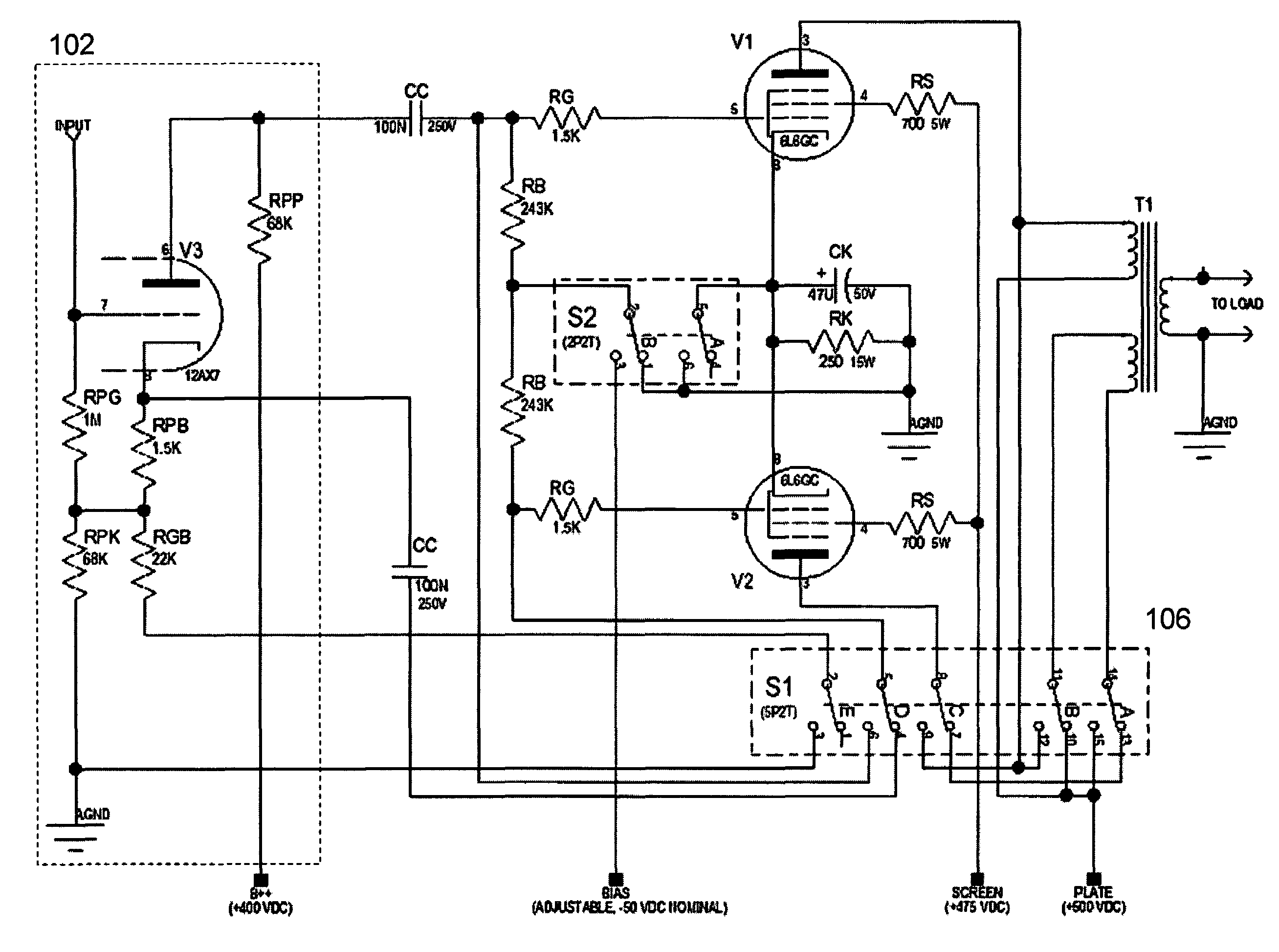
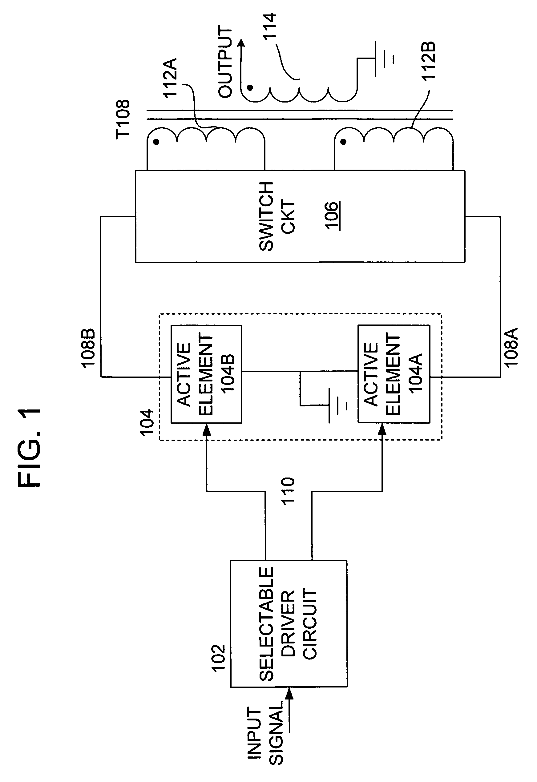
[0022]With reference to the drawings wherein like numerals indicate like elements, there is shown in FIG. 1 a block diagram of an amplifier circuit 100 that is operable to provide selectability in the topology class of the amplifier: between class A operation and class A / B operation in accordance with one or more aspects of the present invention. The amplifier circuit 100 includes a selectable driver circuit 102, a power amplifier stage 104, a switching circuit 106, and an output transformer stage 108.

[0023]The selectable driver circuit 102 is preferably operable to receive an input signal (such as from upstream circuitry of an electric guitar preamplifier) and to produce one or more drive signals 110 suitable for biasing at least the active components of the power amplifier stage 104. As will be discussed in more detail herein below, the selectable driver circuit 102 is operable to produce a single-phase drive signal 110 for class A operation or first and second drive signals (each...


PUM


Abstract

Methods and apparatus contemplate: an output transformer having at least first and second separate primary windings and at least one secondary winding, each winding including a first (in phase) end and a second (out of phase) end; at least first and second active elements, each having at least a pair of power terminals and a control terminal, one power terminal of each active element being coupled to a common node; and a switching circuit operable to change a circuit configuration of the first and second primary windings and the active elements between a class A mode and a class A / B mode.

Description

BACKGROUND OF THE INVENTION[0001]The present invention relates to methods and apparatus for selectively changing a circuit configuration of a power amplifier stage, e.g., for a guitar amplifier, between class A and class A / B.[0002]Designers of guitar amplifiers, up until the late 1950's, focused on creating inexpensive amplifiers with very little distortion. This was not an easy task as solid state devices were not generally available and nearly all amplifiers were designed and built using vacuum tubes. Although tube amplifiers inherently have more distortion than solid state amplifiers, the early amplifier pioneers tried in vain to produce amplifiers with little or no distortion. Most of their designs had a high order of distortion, especially second harmonic distortion, because of the fact that most used a Class A power amplifier topology.[0003]In the context of electric guitar amplification, the existence of harmonic distortion in the amplifier is not undesirable. Indeed, it has ...

Claims


Application Information

Patent Timeline
Patent Type & Authority Patents(United States)
IPC IPC(8): H03F3/26
CPCH03F1/0261H03F3/02H03F3/181H03F3/20H03F3/211H03F3/28H03F3/30H03F3/26H03F2203/21145H03F2200/27H03F2200/421H03F2200/541
Inventor FIELDS, JOHN CALVINPEAVEY, HARTLEY D.
Owner PEAVEY ELECTRONICS
Why Eureka
Try Eureka