Exhaust gas housing of a thermal engine

a technology of exhaust gas and thermal engine, which is applied in the direction of liquid fuel engines, machines/engines, mechanical equipment, etc., can solve the problems of material defects and failure of thermal engines, and achieve the effect of no impairment of the operating concep

Inactive Publication Date: 2006-06-06
ANSALDO ENERGIA IP UK LTD
View PDF15 Cites 56 Cited by
  • Summary
  • Abstract
  • Description
  • Claims
  • Application Information

AI Technical Summary

Benefits of technology

[0012]It is particularly expedient to use an external fan for introducing the cooling medium into the carrying ribs, since the temperature of the carrying structure in the exhaust gas housing can thereby be adjusted independently of other gas turbine parameters.
[0013]Furthermore, it is beneficial to equip the carrying ribs and the carrying struc...

Problems solved by technology

In the event of insufficient protection for the exhaust gas housing and of the associated carrying structure, in particular the carrying ribs, from the high thermal stresses caused by the hot exhaust gases, problems may arise with material creeping ac...

Method used


Image

  • Exhaust gas housing of a thermal engine
  • Exhaust gas housing of a thermal engine
  • Exhaust gas housing of a thermal engine

Examples


Embodiment Construction

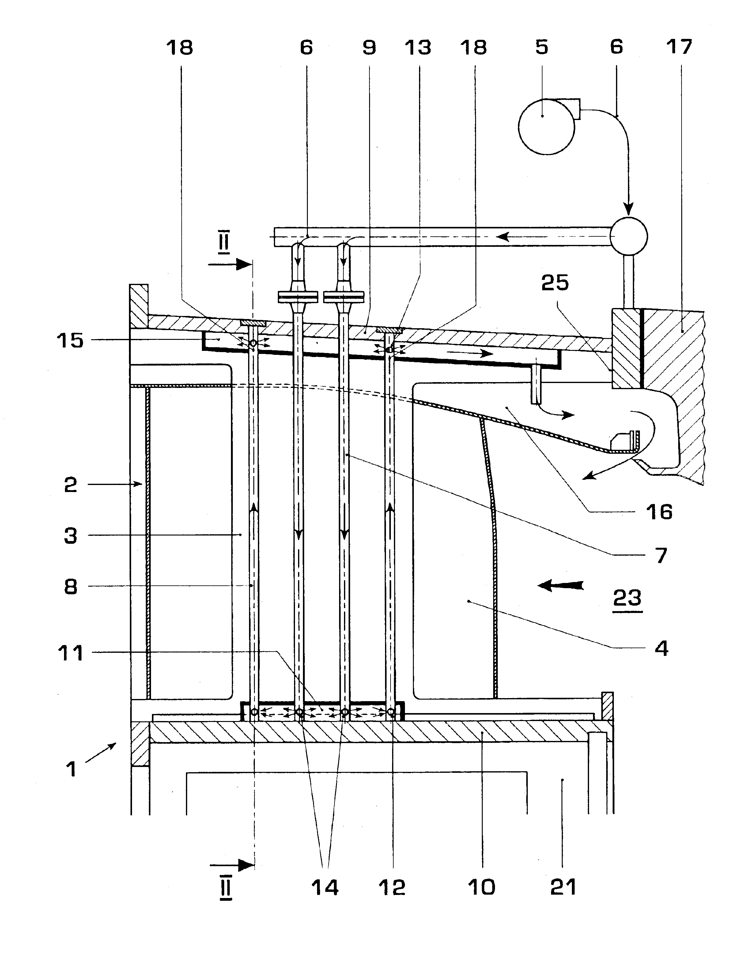
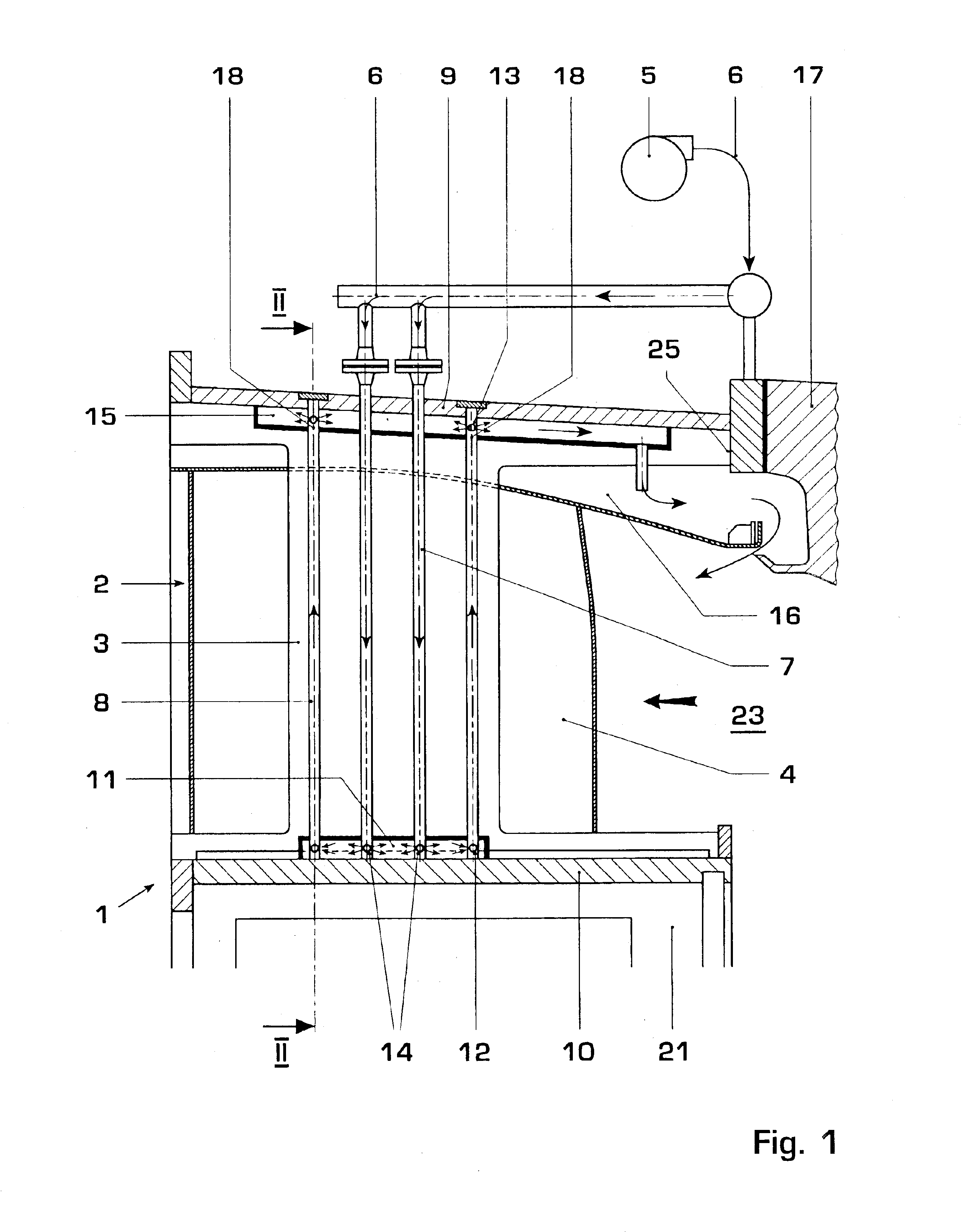
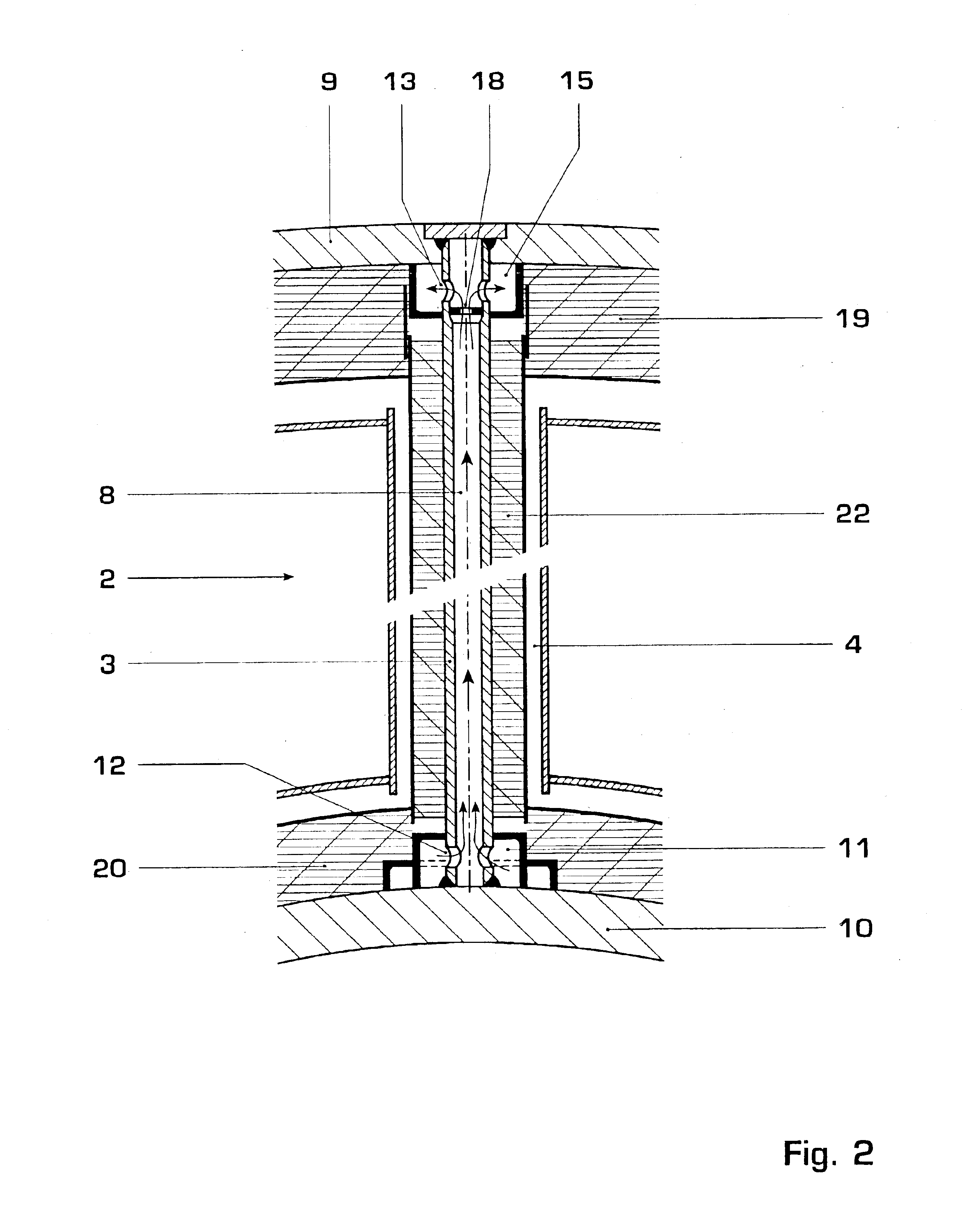
[0020]FIG. 1 shows the exhaust gas housing (1) of a thermal engine, here, for example, an axial-throughflow gas turbine plant. The exhaust gas housing (1) is in this case arranged downstream of the gas turbine, not illustrated, and is flanged to a housing (17) of the gas turbine by means of a flange (24). The exhaust gas housing (1) surrounds a bearing housing (21) for a rotor, not illustrated, of the gas turbine plant. The exhaust gas housing (1) comprises a radially outer exhaust gas housing casing (9) and a radially inner hub-side exhaust gas housing casing (10), which delimit an annular exhaust gas duct (23), carrying ribs (3) and a thermally insulating lining (4), these components forming an exhaust gas diffuser (2) for routing the exhaust gas flow. The carrying ribs (3) are in this arranged in a star-shaped manner in the exhaust gas diffuser (2) and transfer the bearing-body and the rotor weight of the gas turbine plant, said weight acting on the inner exhaust gas housing casi...


PUM


Abstract

In an exhaust gas housing (1) of a thermal engine, a radially outer housing casing (9) and a radially inner housing casing (10) arranged on the hub side are connected to one another via at least one thermally insulated carrying rib (3) acted upon by a cooling medium. A carrying rib (3) has at least two passage ducts (7) and (8) for the cooling medium, at least one passage duct (7) possessing a cooling medium supply (6) and at least one passage duct (8) possessing a cooling medium outlet (12), and these passage ducts (7) and (8) being in communicating connection in the radially inner hub-side end region via a deflection duct (11). The cooling medium is led from an external pressure source (5) through the carrying rib (3) to the region of the deflecting duct (11) arranged on the hub-side casing (10) and from there through the carrying rib (3) back again into a collecting duct (15) which issues preferably into an annular duct (26) for cooling the exhaust gas housing flange (24).

Description

[0001]This application claims priority under 35 U.S.C. §§119 and / or 365 to Appln. No. 102 05 429.0 filed in Germany on Feb. 9, 2002; the entire content of which is hereby incorporated by reference.FIELD OF THE INVENTION[0002]The invention relates to an exhaust gas housing of a thermal engine, consisting of a radially outer housing casing and, at a distance from the latter, a radially inner housing casing, said casings delimiting an annular exhaust gas duct, and of a plurality of carrying ribs which are cooled by means of a fluid cooling medium and which bridge the exhaust gas duct.DISCUSSION OF BACKGROUND[0003]It is known from DE 44 35 322 A1 subsequently to flange an exhaust gas housing onto the housing of a gas turbine. The exhaust gas housing consists essentially of a hub-side annular inner part and of an annular outer part which are connected to one another via a plurality of radial carrying ribs arranged uniformly over the circumference. The outlet-side mounting of the turbine ...

Claims


Application Information

Patent Timeline
IPC IPC(8): F02C7/12F01D25/14F01D25/28F01D25/30F02C7/00
CPCF01D25/145F01D25/30F01D25/28
Inventor BAXTER, ANDREWNAVROTSKY, VLADIMIRMIHELIC, MIRJANAROTHBRUST, MATTHIAS
Owner ANSALDO ENERGIA IP UK LTD
Why Eureka
Try Eureka