Progressive stamping die

a technology of progressive stamping and stamping parts, which is applied in the direction of shaping safety devices, forging/pressing/hammering apparatuses, and shaping tools, etc., can solve problems such as leakage of radiators

Inactive Publication Date: 2006-06-06
COWIE RALPH
View PDF7 Cites 10 Cited by
  • Summary
  • Abstract
  • Description
  • Claims
  • Application Information

AI Technical Summary

Problems solved by technology

Ring members which are out of tolerance can cause openings in the conduits causing leaks in the radiator which are unacceptable.

Method used


Image

  • Progressive stamping die
  • Progressive stamping die
  • Progressive stamping die

Examples


Embodiment Construction

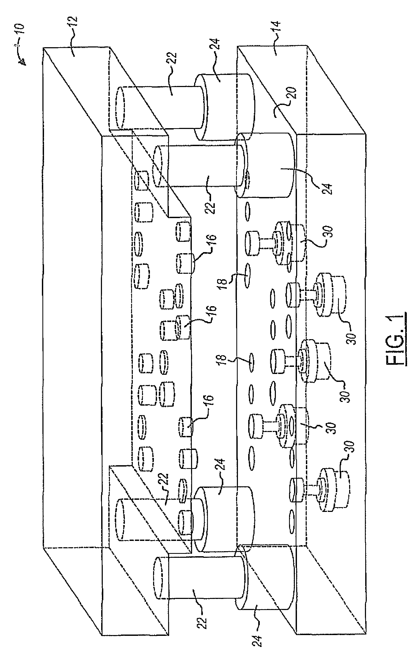
[0016]A progressive stamping die partially in accordance with the present invention is illustrated schematically in FIG. 1 and referred to generally by the reference numeral 10. The progressive die 10 includes an upper or first die member 12 and a lower or second die member 14. In general, the upper die member 12 includes a plurality of punch members 16, which are operated by a punch shoe or the like (not shown) when the progressive stamping die 10 is positioned in a stamping (press) machine. The lower die member 14 typically includes a number of openings or chutes 18 which are used for removing scrap or products from the work piece which is passed along the upper surface 20 in between the two stamping die members 12 and 14.

[0017]The progressive stamping die 10 also includes an alignment mechanism which comprises a plurality of postmembers 22 which are attached to the upper die member 12 and a plurality of cup or socket members 24 which are provided as part of the lower die member 1...


PUM

PropertyMeasurementUnit
thicknessaaaaaaaaaa
flatnessaaaaaaaaaa
dimensionsaaaaaaaaaa

Abstract

A progressive stamping die system and method of operation providing dimensionally accurate flat stamped parts. A biasing mechanism is provided in actual alignment with a coin punch member in order to accurately control the configuration and planar accuracy of the stamped parts being formed.

Description

BACKGROUND OF INVENTION[0001]A system and method for producing a stamped part from a progressive die, particularly a stamped part with multiple operations from coil stock material.[0002]Progressive dies used to make stamped parts, particularly metal parts, are in common use today. Stamped parts made from progressive dies are in common use in many industries, such as the automobile industry. These parts include, for example, door bracket members.[0003]One of the uses for stamped metal parts today relates to the formation of cooling conduits in radiators for vehicles. Stamped ring members similar to washers are formed by progressive die stamping processes, and then coated with copper and braised together to form a radiator conduit.[0004]Stamped ring members used for forming radiator conduits should have a thickness and flatness within a certain range of tolerances in order to provide a commercially satisfactory conduit. Ring members which are out of tolerance can cause openings in the...

Claims


Application Information

Patent Timeline
Patent Type & Authority Patents(United States)
IPC IPC(8): B21D45/00B21D28/26
CPCB21D37/08B21D28/26
Inventor COWIE, RALPH
Owner COWIE RALPH
Why Eureka
Try Eureka