Reduced recoil anti-armor gun

a recoil energy and anti-armor technology, applied in the direction of weapons, missile propulsion, weapon components, etc., can solve the problems of limited recoil range towards the rear of the rifle, no momentum transfer has been recruited into any performance function or benefit, and simply wasted, so as to reduce the recoil impulse and recoil energy, and reduce the momentum and recoil energy

Inactive Publication Date: 2006-06-06
UNITED STATES OF AMERICA THE AS REPRESENTED BY THE SEC OF THE ARMY
View PDF9 Cites 12 Cited by
  • Summary
  • Abstract
  • Description
  • Claims
  • Application Information

AI Technical Summary

Benefits of technology

[0026]The present invention satisfies this need to further reduce recoil impulse and recoil energy. It comprises a means for modifying small caliber weapons of less than 40 mm, and in particular the 25 mm and 0.50 calibers, to function from the open bolt position, with advanced primer ignition, to coun

Problems solved by technology

Axial barrel springs connect the barrel to the external housing, biasing the barrel towards the battery position at the front of the rifle, and giving it limited motion range towards the rear of the rifle.
However this momentum transfer has not been recruited into any performance function or benefit.
It is simply wasted.
The bolt carrier on its bottom distal end is added with a pivotal cocking lever pointing downward at the trigger a

Method used


Image

  • Reduced recoil anti-armor gun
  • Reduced recoil anti-armor gun
  • Reduced recoil anti-armor gun

Examples


Embodiment Construction

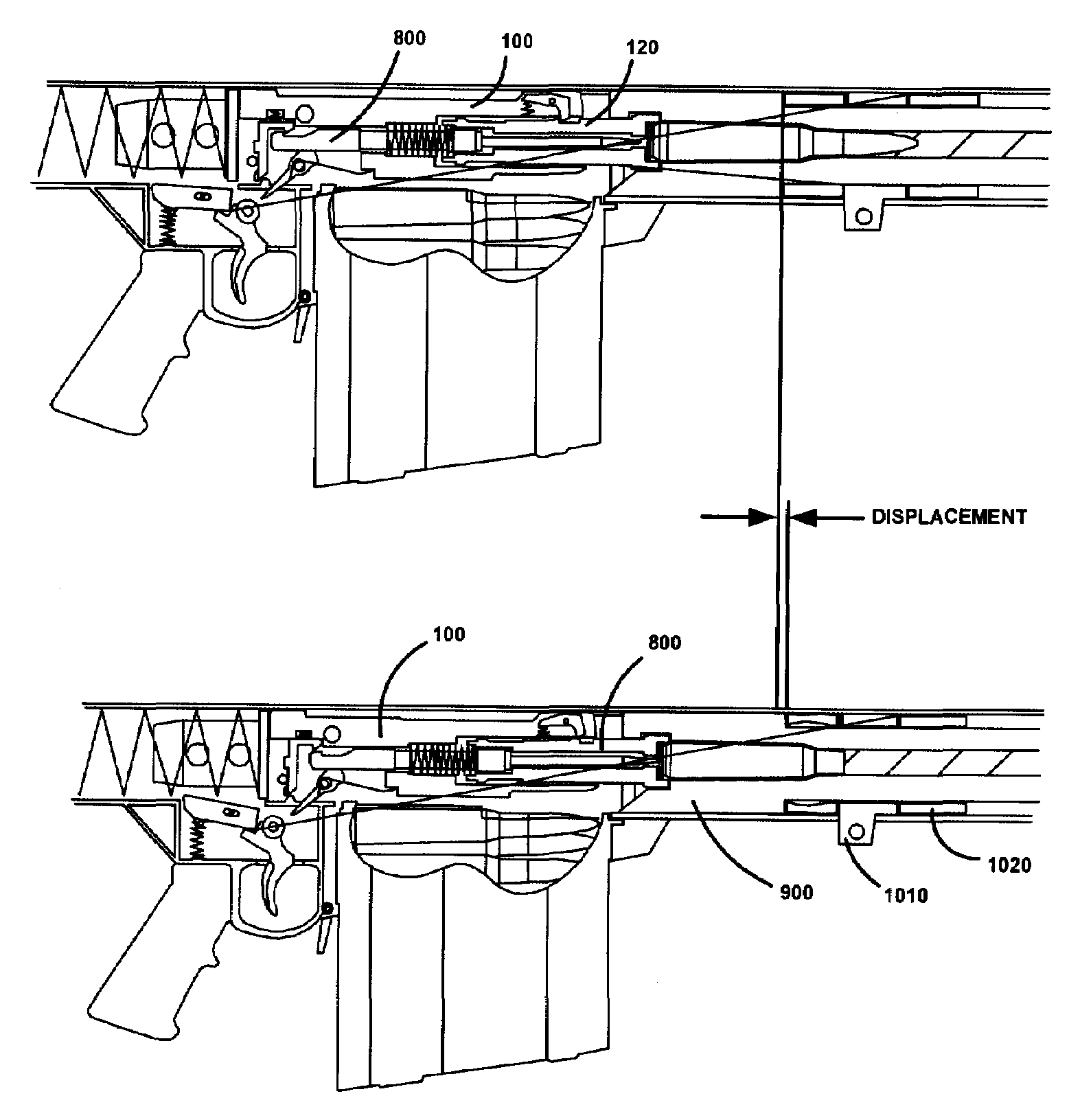
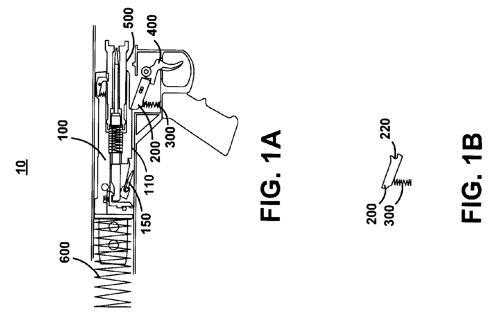
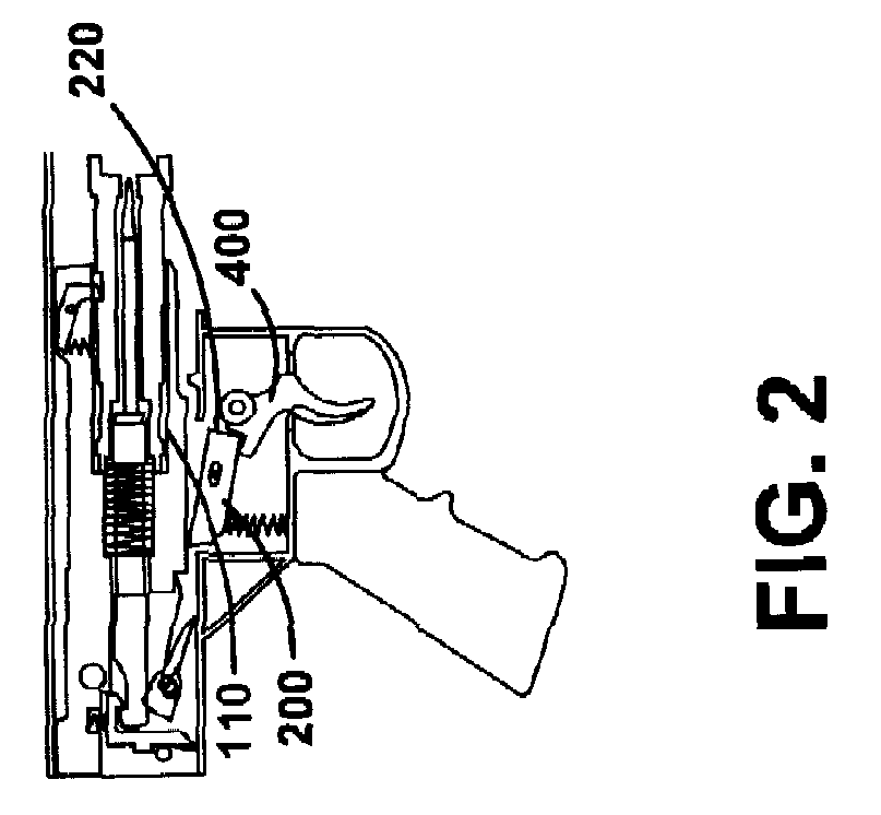
[0045]FIG. 1 illustrates a weapon 10 that comprises a down facing sear notch 110 in a bolt carrier 100, a pivotal bolt carrier sear 200 with a proximal slanted latch notch 220 with a rearward translational spring bias at the pivot, a bolt carrier sear spring 300 acting on the bolt carrier sear with a clockwise bias, a bolt carrier rear mounted firing pin cocking lever 150 with a clockwise rotational spring bias, a pivotal trigger 400, a firing pin sear trip cam 500, and a new drive spring 600 with a spring constant higher than conventional.

[0046]During operation, the bolt carrier 100 is pulled fully to the rear by the means of either a recoil or charging handle (not shown) currently employed in the weapon design, compressing the drive spring 600. As bolt carrier 100 is pulled to the rear, helical compression bolt carrier sear spring 300 forces bolt carrier sear 200 into an elevation capable of engaging bolt carrier sear notch 110 at the bottom of bolt carrier 100. When the bolt carr...


PUM


Abstract

An improved Barrett anti-armor gun that is modified to function from the open bolt with advanced primer ignition, wherein the forward momentum of the recoiling masses at the moment of firing offset a significant portion of the recoil impulse from firing. The modification reduces the recoil energy absorbed by the shooter.

Description

CROSS REFERENCE TO RELATED APPLICATIONS[0001]The present application is a continuation-in-part of application serial number 10 / 708,454 filed Mar. 4, 2004 now abandoned which in turn claims priority under 35 USC 119(e) of provisional application 60 / 320,000 filed Mar. 11, 2003, the entire file wrapper contents of both which applications are hereby incorporated by reference as though fully set forth at length herein.GOVERNMENT INTEREST STATEMENT[0002]The invention described herein may be manufactured and used by, or for the Government of the United States for governmental purposes without the payment of any royalties thereon.FIELD OF INVENTION[0003]The present invention relates in general to the field of anti-armor rifles, and particularly to modifications to the Barrett Model 82A1 semi-automatic rifle and derivative family of weapons to reduce recoil. More specifically, this invention relates to a mechanism that counteracts a significant portion of the recoil energy in a rifle, and pa...

Claims


Application Information

Patent Timeline
IPC IPC(8): F41A3/54F41A3/78
CPCF41A1/08F41A3/78F41A3/54
Inventor DINDL, FRANKAPONTE, SERGIO
Owner UNITED STATES OF AMERICA THE AS REPRESENTED BY THE SEC OF THE ARMY
Why Eureka
Try Eureka