
Compression ignition internal combustion engine

a technology of compression ignition and internal combustion engine, which is applied in the direction of ignition automatic control, electrical control, exhaust treatment electric control, etc., can solve the problems of increased cost, poor mountability of the engine on the vehicle, and complicated system

Inactive Publication Date: 2006-06-06
HITACHI LTD
View PDF23 Cites 18 Cited by
  • Summary
  • Abstract
  • Description
  • Claims
  • Application Information

AI Technical Summary

Benefits of technology

The present invention provides a compression ignition internal combustion engine that can control the self-ignition timing of an air-fuel mixture in a wide engine operating range with respect to a load and a revolution speed without changing the shape of the combustion chamber to a large extent. This is achieved by injecting an ignition trigger factor directly into the combustion chamber at an arbitrary timing in a state in which the intake valve and the exhaust valve are closed, depending on operating conditions of the engine. The control means can include at least one of injection timing, injection amount, and injection pressure of the ignition trigger factor. This allows for proper ignition timing to be controlled in a wide engine operating range with respect to a load and a revolution speed.

Problems solved by technology

In the internal combustion engine disclosed in JP,A 10-196424, however, because an increase in the temperature and pressure in the combustion chamber is controlled by additionally providing the control piston to vary the capacity of the combustion chamber, problems arise in that a resulting substantial modification in shape of the engine brings about a more complicated system, poor mountability on a vehicle, and a cost increase.

Method used


Image

  • Compression ignition internal combustion engine
  • Compression ignition internal combustion engine
  • Compression ignition internal combustion engine

Examples


first embodiment

[0033]The construction and the operation of a compression ignition internal combustion engine according to the present invention will be described below with reference to FIGS. 1 to 8.

[0034]First, the construction of the compression ignition internal combustion engine according to this embodiment will be described below with reference to FIGS. 1 and 2.

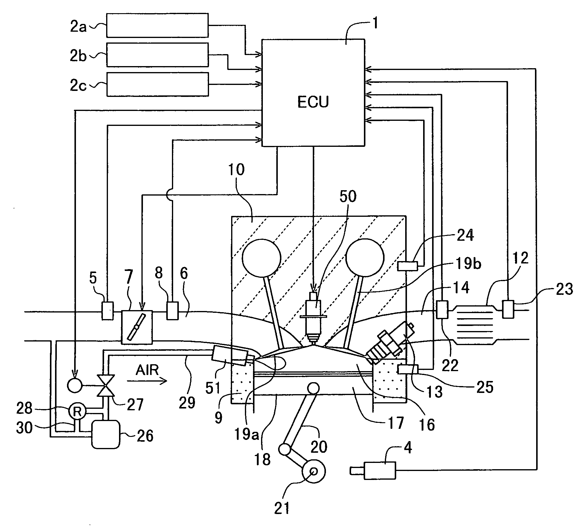
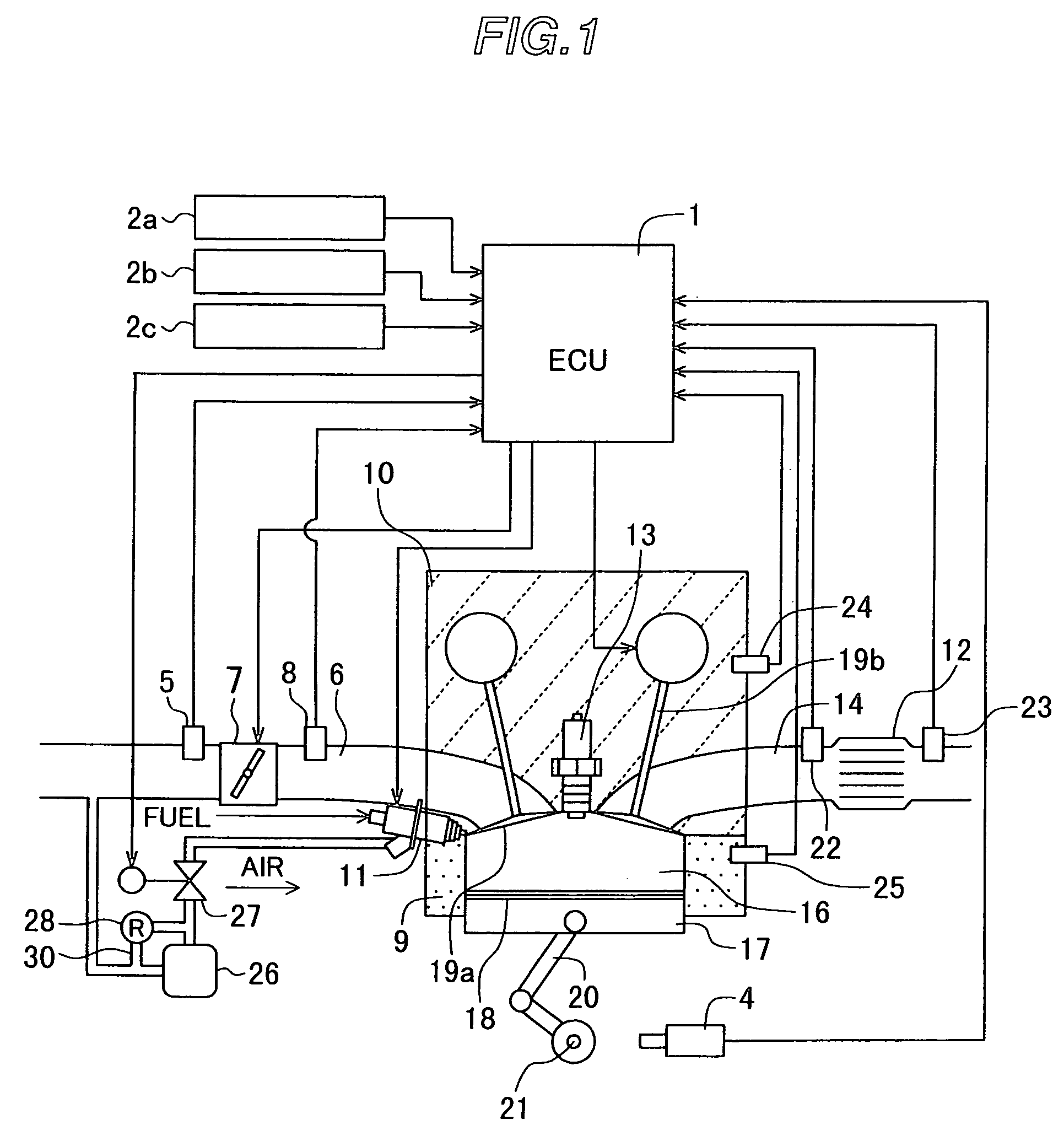
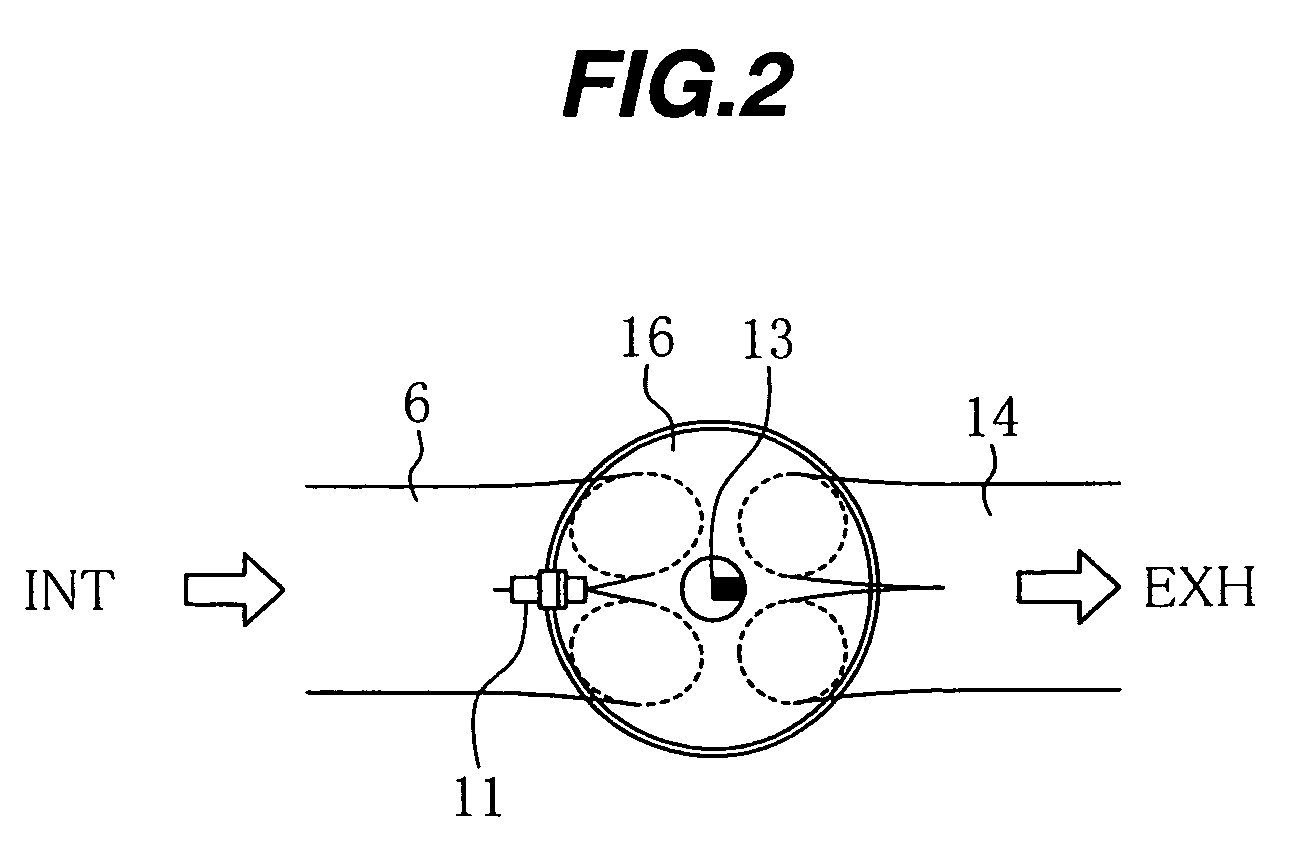
[0035]FIG. 1 is a block diagram showing the construction of the compression ignition internal combustion engine according to the first embodiment of the present invention, and FIG. 2 is a plan view showing the construction of a combustion chamber and thereabout in the compression ignition internal combustion engine according to the first embodiment of the present invention.

[0036]As shown in FIG. 1, an intake port 6 and an exhaust port 14 are communicated with a combustion chamber 16 that is surrounded by a cylinder block 9, a piston 17 and a cylinder head 10. An intake valve 19a is disposed in a joint portion between the combustion cha...

second embodiment

[0087]The construction and the operation of a compression ignition internal combustion engine according to the present invention will be described below with reference to FIGS. 9 to 19.

[0088]First, the construction of the compression ignition internal combustion engine according to this embodiment will be described with reference to FIGS. 9 and 10.

[0089]FIG. 9 is a block diagram showing the construction of the compression ignition internal combustion engine according to the second embodiment of the present invention, and FIG. 10 is a plan view showing the construction of a combustion chamber and thereabout in the compression ignition internal combustion engine according to the second embodiment of the present invention. It is to be noted that the same characters as those in FIGS. 1 and 2 denote the same parts.

[0090]A fuel injection valve 59 used in this embodiment has a plurality of injection holes formed in its nozzle portion. The pressure of fuel 57 is regulated by a fuel pump 58,...

third embodiment

[0131]The construction and the operation of a compression ignition internal combustion engine according to the present invention will be described below with reference to FIGS. 20 to 22.

[0132]First, the construction of the compression ignition internal combustion engine according to this embodiment will be described below with reference to FIG. 20.

[0133]FIG. 20 is a block diagram showing the construction of the compression ignition internal combustion engine according to the third embodiment of the present invention. It is to be noted that the same characters as those in FIG. 1 denote the same parts.

[0134]As shown in FIG. 20, an intake port 6 and an exhaust port 14 are communicated with a combustion chamber 16 that is surrounded by a cylinder block 9, a piston 17 and a cylinder head 10. An intake valve 19a is disposed in a joint portion between the combustion chamber 16 and the intake port 6 to open and close a passage communicating with the combustion chamber 16. An exhaust valve 1...


PUM


Abstract

A compression ignition internal combustion engine includes a combustion chamber, an intake valve 19a, intake port 6, and an exhaust valve 19b. The temperature and pressure in the combustion chamber are increased to self-ignite an air-fuel mixture with the compressive operation of a piston after closing of the intake valve 19a. A fuel injection valve 11 injects pressurized air, serving as an ignition trigger factor, directly into the combustion chamber so that the air-fuel mixture under the expansion stroke of the piston is brought into an ignitable state. An ECU 1 controls the injection timing of the pressurized air depending on the ignition timing. The self-ignition timing can be controlled to a proper timing in a wide engine operating range with respect to a load and a revolution speed without changing the shape of the combustion chamber to a large extent.

Description

TECHNICAL FIELD[0001]The present invention relates to a compression ignition internal combustion engine in which an air-fuel pre-mixture supplied to a combustion chamber is self-ignited with the compressive operation of a piston. More particularly, the present invention relates to a compression ignition internal combustion engine in which the self-ignition timing of an air-fuel mixture can properly be controlled in a wide engine operating range.BACKGROUND ART[0002]JP,A 10-56413 discloses one known example of a compression ignition internal combustion engine employing a combustion mode in which an air-fuel pre-mixture supplied to a combustion chamber is self-ignited with the compressive operation of a piston. The compression ignition internal combustion engine can realize the engine operation in an ultra lean range (at an air-fuel ratio of 80 or more), which has not been realized with gasoline and diesel engines in the past. Also, the compression ignition internal combustion engine c...

Claims


Application Information

Patent Timeline
Patent Type & Authority Patents(United States)
IPC IPC(8): F02B5/00F02M51/00F01N3/20F01N11/00F02B1/12F02B3/06F02B7/00F02B75/12F02B77/08F02D13/02F02D35/00F02D35/02F02D37/02F02D41/00F02D41/14F02D41/30F02D41/34F02F1/42F02M51/06F02M61/16F02M61/18F02M67/02F02M67/06F02P5/04
CPCF02B77/085F02D13/0207F02D35/027F02D37/02F02D41/0002F02D41/3017F02D41/3041F02D41/345F02F1/4214F02M61/162F02M61/1806F02M61/1853F02M67/02F02M67/06F01N11/002F01N3/20Y02T10/47F02B1/12F02B3/06F02B7/00F02B2075/125F02D35/021F02D2041/3088F02D2200/501F02D2250/18F02M51/06F02M51/061F02P5/045Y02T10/18Y02T10/44Y02T10/123Y02T10/42Y02T10/12Y02T10/40
Inventor YAMAOKA, SHIROOOSUGA, MINORUNOGI, TOSHIHARUSHIRAISHI, TAKUYAKIHARA, YUUSUKE
Owner HITACHI LTD
Learn More