

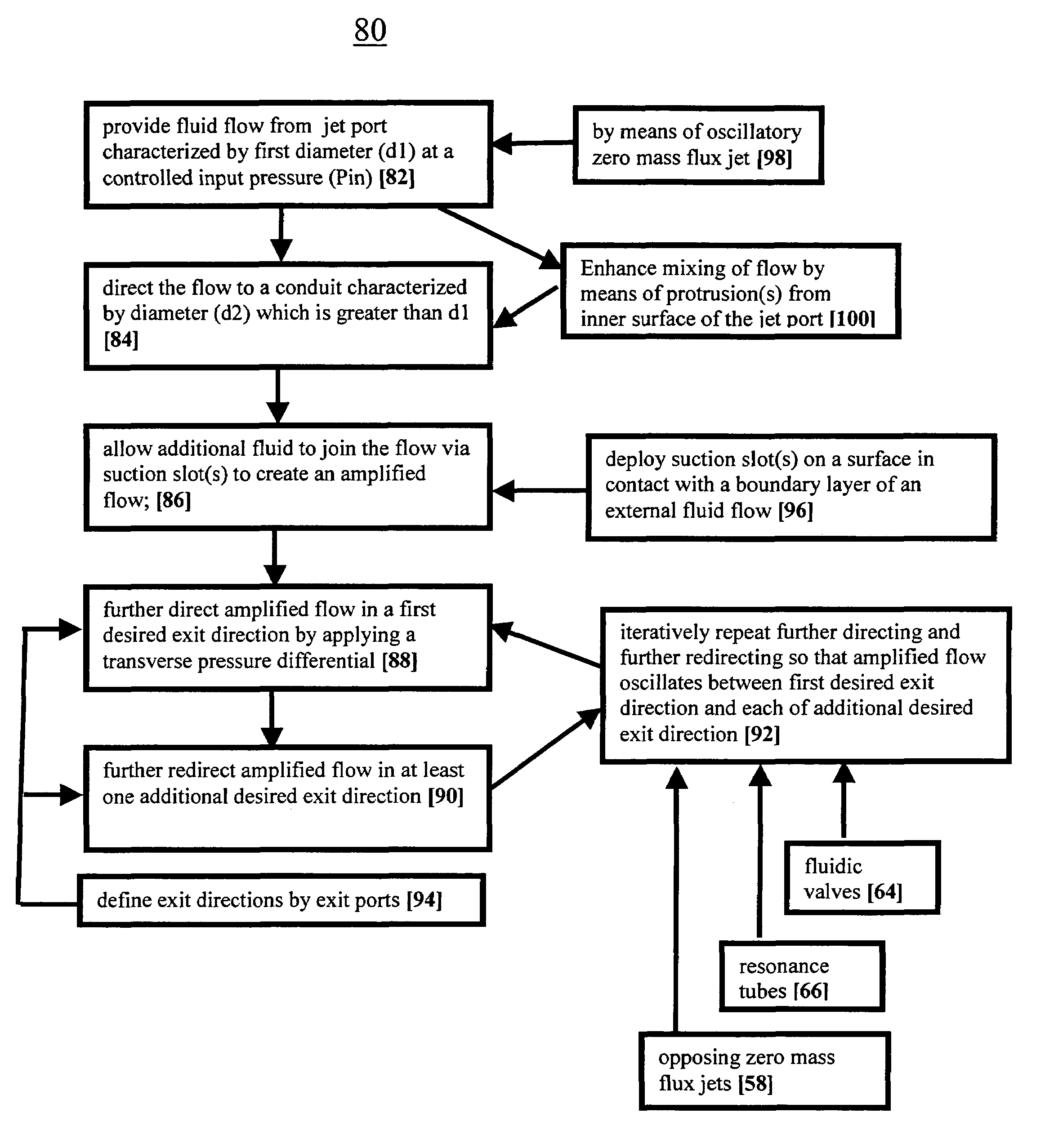
Method and mechanism for producing suction and periodic excitation flow
a technology of excitation flow and suction, which is applied in the direction of mechanical equipment, pipeline systems, thin material processing, etc., can solve the problems of inefficiency of valves, inability to produce the required excitation strength at the appropriate frequency range, and difficulty in incorporation into modem jet propulsion systems
- Summary
- Abstract
- Description
- Claims
- Application Information
AI Technical Summary
Benefits of technology
Problems solved by technology
Method used
Image

Examples
example 1
Alternation of Velocity Profiles by Suction Slots
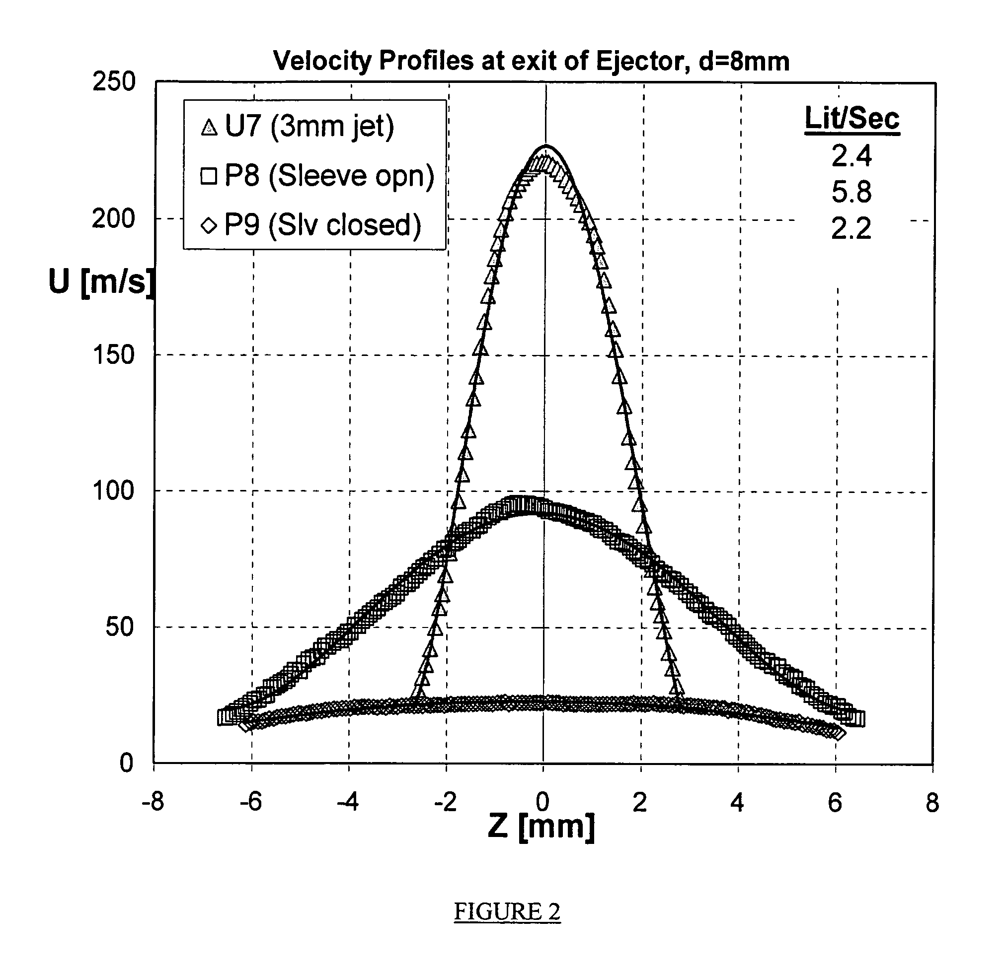
[0088]In order to demonstrate that the theoretical advantages of suction in a mechanism according to the present invention may be realized in practice, a prototype with a d1 of 3 mm and a d2 of 10 mm was constructed. The suction slots were co-linear with the exit of the jet port and angled at 45 degrees with respect to the flow exiting the jet port.
[0089]FIG. 2 shows velocity profiles that were taken at the exit from the d2 jet port without the conduit (highest peak; marked with triangles); with the conduit in place but with the suction slots closed (lowest plot; marked by diamonds); and with the conduit in place and the suction slots open (intermediate peak; marked by squares). This demonstrates that the device is capable of significant amplification of the mass flow rate, as compared to the jet port operating in free air and / or as compared to the jet issuing into the conduit, but with suction ports closed.
[0090]Calculation of flow r...
example 2
De,pmstration of Device Step Response
[0091]The prototype described in example 1 was then equipped with a bilateral exit hood attached to the distal end of the conduit. The exit hood has a rectangular cross section of 8 mm by 10 mm. A deflection device with two 8 mm diameter ducts positioned at the junction between the conduit and the exit hood was employed to generate the required transverse pressure differential. The exit hood is 50 mm long and disperses the exit flow over an inclusive angle of 30 degrees. A deflection wedge with an angle of 15 degrees [8 mm height along all of its length] is insertable in the center of the hood. This serves to divide the hood into two defmed exit ports and to make possible oscillation of exit flow between the ports.
[0092]Initially the deflection wedge was placed 15 mm from the entrance to the hood although the design permits movement of the deflection wedge in 2 directions and makes possible examination of deflection wedge placement on the magnitu...
PUM
 Abstract
Description
Claims
Application Information