System of fluorescence analysis of a field in an illuminated area

a field and illumination technology, applied in the field of analysis in the observation field, can solve the problem of low fluorescence light intensity compared with the normal ambient lighting

Active Publication Date: 2013-12-03
COMMISSARIAT A LENERGIE ATOMIQUE ET AUX ENERGIES ALTERNATIVES
View PDF17 Cites 8 Cited by
  • Summary
  • Abstract
  • Description
  • Claims
  • Application Information

AI Technical Summary

Benefits of technology

[0007]An object of the present invention is to provide a system for observing fluorescence light in the presence of an ambient illumination which overcomes at least some of the disadvantages of prior systems.
[0009]An object of an embodiment of the present invention is to provide a system which avoids the use of expensive filterings.
[0010]An object of an embodiment of the present invention is to provide a system which enables to freely select fluorescent elements having optical characteristics that may be very different.

Problems solved by technology

A problem which arises for the analysis of fluorescent areas is that, generally, the fluorescence light intensity is very low as compared with the normal ambient lighting.

Method used


Image

  • System of fluorescence analysis of a field in an illuminated area
  • System of fluorescence analysis of a field in an illuminated area
  • System of fluorescence analysis of a field in an illuminated area

Examples


Embodiment Construction

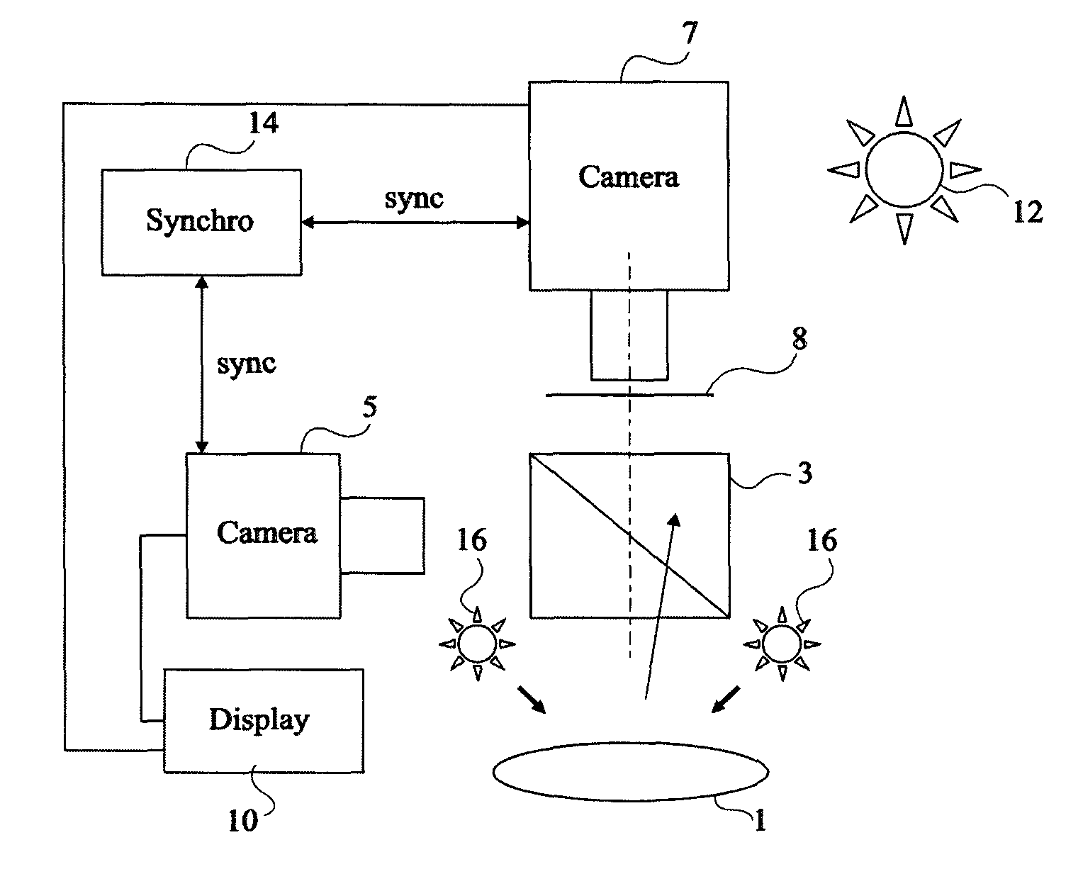
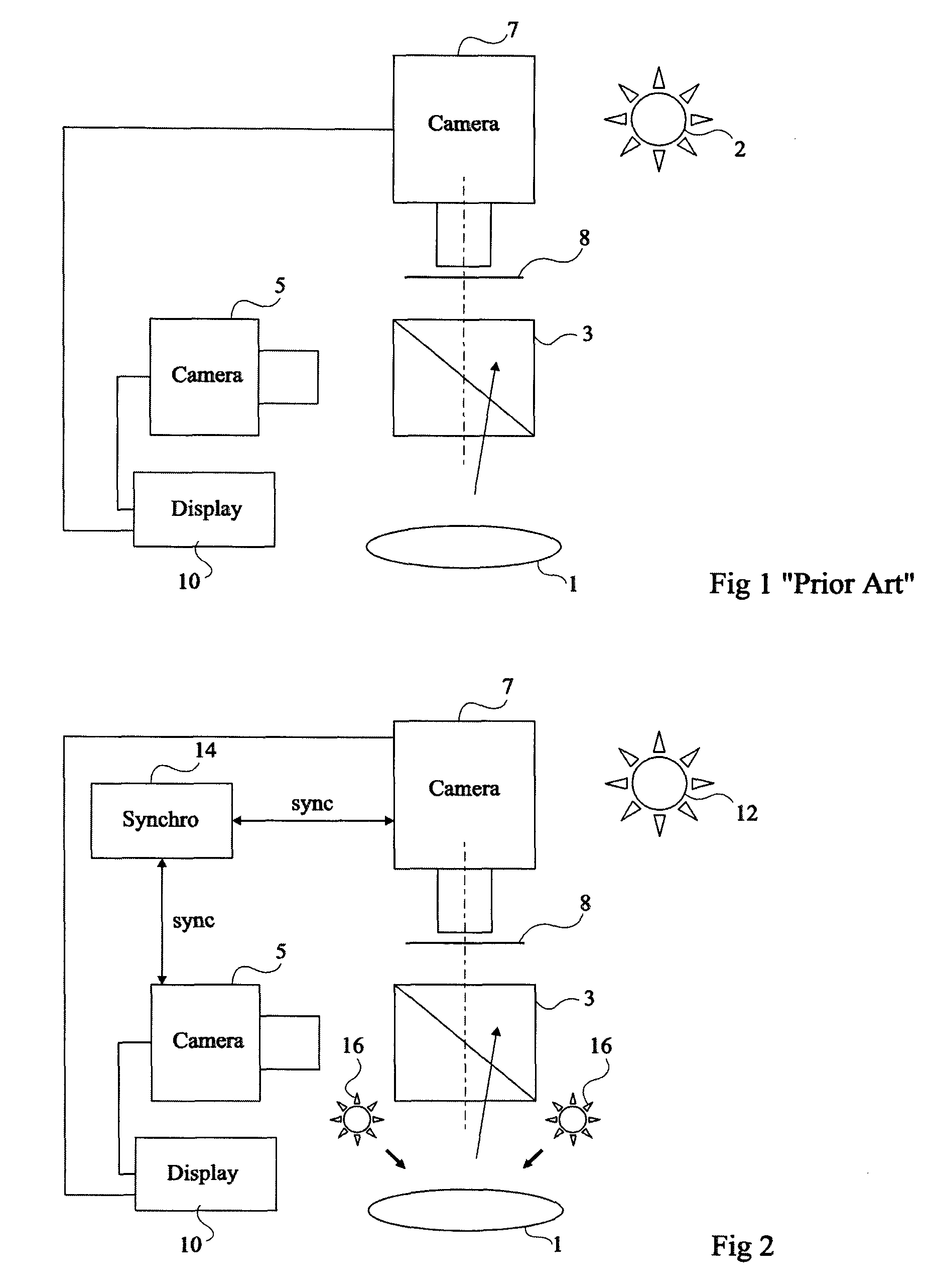
[0023]FIG. 1 shows an area to be observed or operation area 1 arranged in an operating room illuminated by an ambient illumination source 2, generally a white light source formed of an assembly of incandescent lamps. The operation field is observed with the help of a beam splitter 3, on the one hand, by an optional color camera 5, and on the other hand by a camera 7 sensitive to the sole fluorescence light of operation area 1. This fluorescence light for example results from an illumination by a specific light source, not shown. A filter 8 isolates the spectral range in which the fluorescence light is emitted. Preferably, the images of cameras 5 and 7 are superposed by processing means on a display screen 10 which shows, on the one hand, the entire operation area, and on the other hand the regions of this area more specifically rich in fluorescent elements, these regions being for example marked with a specific color or with specific symbols. Thus, a surgeon which observes the scene...


PUM


Abstract

A system of analysis with the naked eye and by fluorescence of a field in an illuminated area comprising a periodically-excited first low-remanence white light illumination source; a second light source for exciting fluorescent elements located in said field, active at least during part of the time periods when the first source is off; and a fluorescence analysis device active during time periods when the first source is off and the second source is on.

Description

BACKGROUND OF THE INVENTION[0001]1. Field of the Invention[0002]The present invention relates to the analysis in an observation field of the radiation of fluorescent elements, the observation field being arranged in an illuminated area so that this field and the surrounding areas can also be directly observed in a natural fashion.[0003]2. Discussion of the Related Art[0004]The state of the art and the present invention will essentially be discussed hereafter in the context of a medical or veterinary application of the present invention, where the illuminated area is an operating room or another medical or veterinary intervention room, for example, a dermatological intervention room. The observation field or operation area then is a portion of a patient's body, with locations which have fixed fluorescent elements indicative of specific physiological characteristics. For example, on the skin, areas affected by disease or attacked by parasites are likely to fix more fluorescent element...

Claims


Application Information

Patent Timeline
Patent Type & Authority Patents(United States)
IPC IPC(8): G01J1/58A61B5/00
CPCA61B1/0638A61B5/0059A61B5/0071A61B5/444G01N21/6456A61B1/043A61B1/0684G01N21/64G01N2021/6419G01N2021/6441A61B1/0655
Inventor MOY, JEAN-PIERRERIZO, PHILIPPEDA SILVA, ANABELLA
Owner COMMISSARIAT A LENERGIE ATOMIQUE ET AUX ENERGIES ALTERNATIVES
Why Eureka
Try Eureka