
Article separation and conveyance device

A technology for conveying devices and articles, applied in the direction of conveyors, conveyor objects, vibrating conveyors, etc., to achieve the effect of simple structure

Inactive Publication Date: 2014-01-01
SHINKO ELECTRIC CO LTD
View PDF6 Cites 9 Cited by
  • Summary
  • Abstract
  • Description
  • Claims
  • Application Information

AI Technical Summary

Problems solved by technology

[0011] In order to solve the above-mentioned problems, the object of the first invention in this application is to provide a product that can transport the sorted items in any direction while sorting the items, and can be easily used in the production line. The item distinguishing conveying device

Method used


Image

  • Article separation and conveyance device
  • Article separation and conveyance device
  • Article separation and conveyance device

Examples


no. 1 Embodiment approach

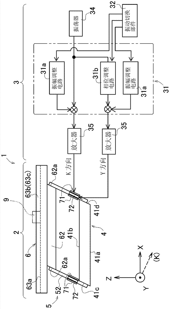
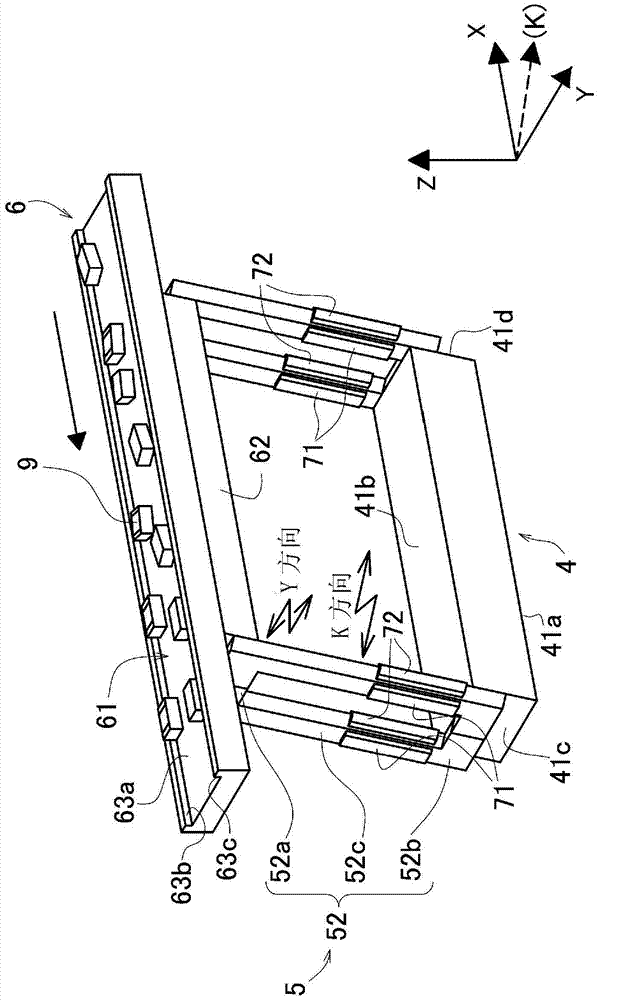
[0053] Such as figure 1 As shown, the article sorting and conveying device 1 of the first embodiment is generally composed of a mechanism unit 2 and a control system unit 3 . The control system unit 3 is configured to apply periodic vibration forces in the K and Y directions to the mechanical unit 2 by controlling the piezoelectric elements 71 and 72 incorporated in the mechanical unit 2 as described later to generate vibration.

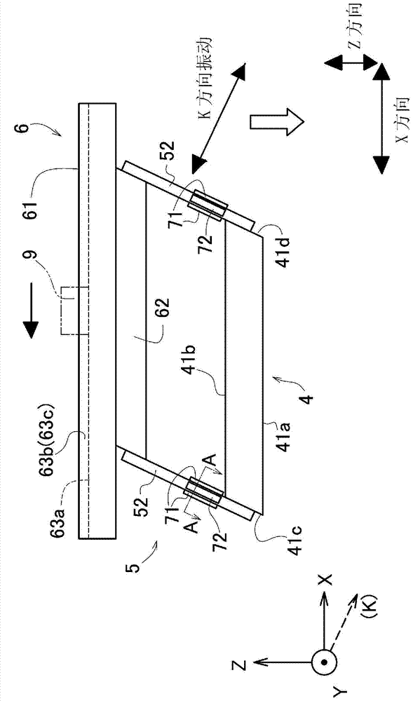
[0054] Here, in the present embodiment, the K direction refers to a direction perpendicular to the attachment surface of the piezoelectric element 71 to the elastic supporting member 52 , and the Y direction refers to a direction perpendicular to the drawing. In addition, the X and Z directions described later are also defined as indicated by the coordinate axes shown on the lower left in the figure. Therefore, the K direction can be said to be a direction parallel to the XZ plane, which is a plane having X-direction and Z-direction components. H...

no. 2 Embodiment approach

[0097] Such as Figure 13 As shown, the article sorting and conveying device 201 of the second embodiment is generally composed of a mechanism unit 202 and a control system unit 203 . The control system unit 203 is configured to apply vibrations in the K and Y directions to the mechanism unit 202 by controlling the piezoelectric elements 281 to 282 as vibrating members incorporated in the mechanism unit 202 as will be described later. Periodic initiating force and vibration.

[0098] Here, also in this embodiment, the Y direction refers to the horizontal direction perpendicular to the paper surface in the drawing, and the K direction refers to the rod-shaped spring member 272 provided obliquely from the vertical direction in the same manner as in the above-mentioned first embodiment. Orthogonal and perpendicular to the above-mentioned Y direction. In addition, the X direction mentioned later means the horizontal direction orthogonal to the said Y direction, and the Z directi...


PUM


Abstract

Provided is an article separation and conveyance device that can separate a plurality of articles on a conveyance surface and convey the articles in different directions. The article separation and conveyance device (1) conveys articles (9) using the vibration of a movable body (6) provided via an elastic support means (5), and the device comprises the following: a first excitation means (71) for imparting a periodic excitation force in a direction inclined from the vertical direction relative to the movable body (6); a second excitation means (72) for imparting a periodic excitation force in a direction intersecting that of the periodic excitation force caused by the first excitation means (71); and a vibration-controlling means (31) for causing the periodic excitation forces caused by each of the excitation means (71, 72) to have a phase difference and to occur simultaneously at the same frequency, and creating an elliptical vibration trajectory for the movable body (6). The vibration trajectory of the movable body (6) is set by the vibration-controlling means (31) so that articles having different coefficients of friction are conveyed in different directions, and as a result the articles (9) are separated and conveyed atop the movable body (6).

Description

technical field [0001] The invention relates to an article sorting conveying device capable of conveying a plurality of articles by vibration and distinguishing the plurality of articles. Background technique [0002] Conventionally, many article conveying devices such as linear feeders using vibration are known, and an article conveying device such as Patent Document 1 embodying such a technology is disclosed. [0003] This article conveying device is configured to cause the movable body to generate elliptical vibrations by applying vibrations of the same frequency in the vertical and horizontal directions to the movable body having a track for conveying articles, and to set the vibrations in each direction according to the coefficient of friction. The phase difference can make the conveying direction different. By using this article conveying device, two kinds of articles with different friction coefficients can be placed on the conveying surface at the same time, and by ...

Claims


Application Information

Patent Timeline
Patent Type & Authority Applications(China)
IPC IPC(8): B65G27/24B07C5/34B65G27/32B65G47/14
CPCB65G27/24B65G27/32B65G47/26B07B13/113B07C5/34B65G47/14
Inventor 木村哲行村岸恭次
Owner SHINKO ELECTRIC CO LTD
Learn More