
Sheet discharge device and sheet processing device using the same

a discharge device and processing device technology, applied in the direction of thin material processing, electrographic process apparatus, instruments, etc., can solve the problems of difficult for users to change the construction of the device is likely to be complicated, and the accommodable number of discharge sheets is inevitably limited. , to achieve the effect of enhancing the transportability, and reducing the transport resistan

Inactive Publication Date: 2006-06-06
FUJIFILM BUSINESS INNOVATION CORP
View PDF6 Cites 8 Cited by
  • Summary
  • Abstract
  • Description
  • Claims
  • Application Information

AI Technical Summary

Benefits of technology

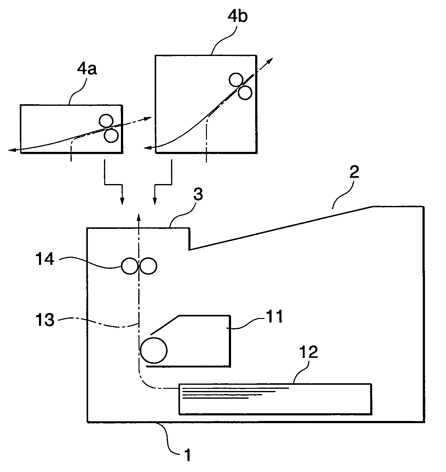
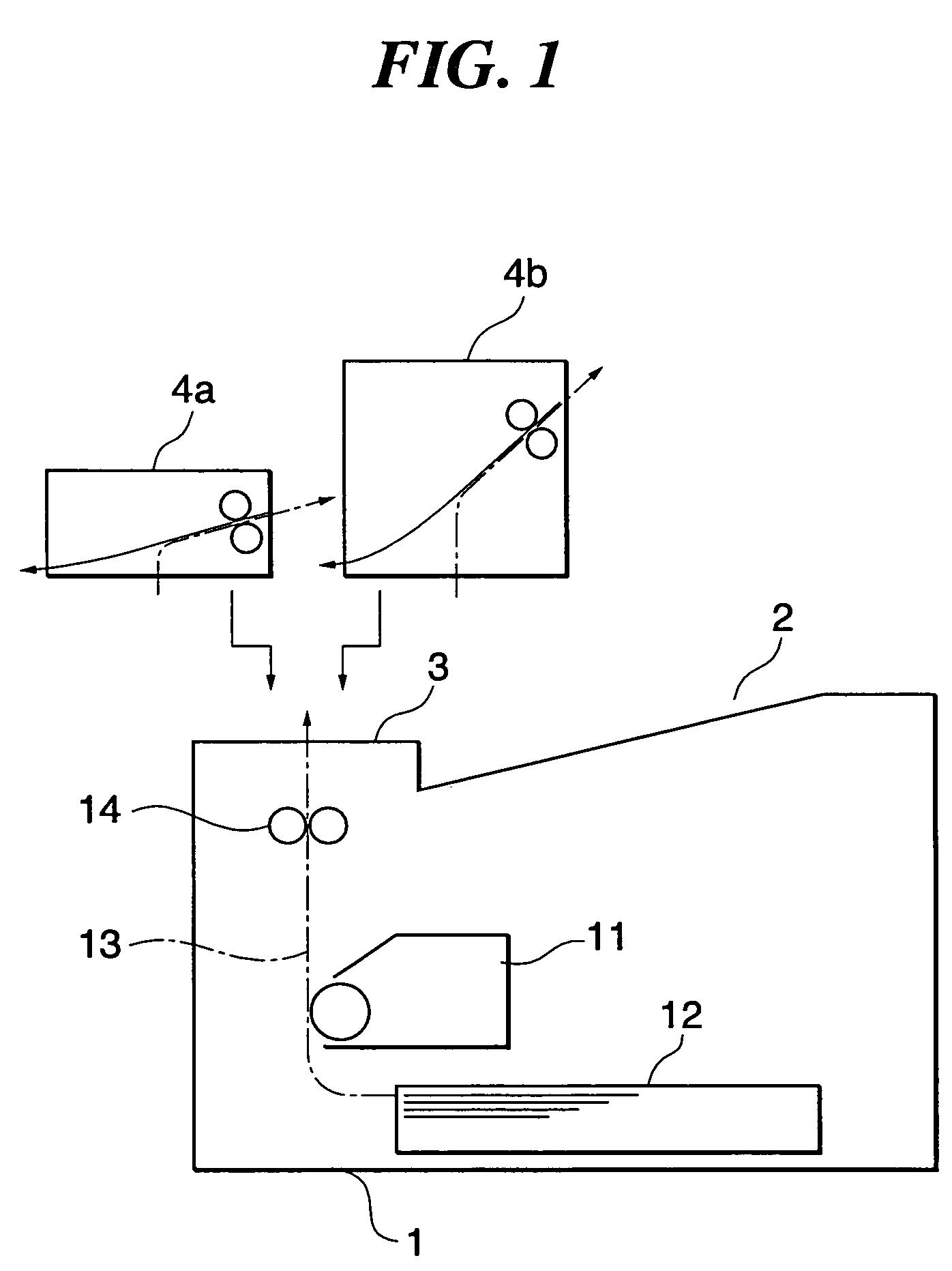
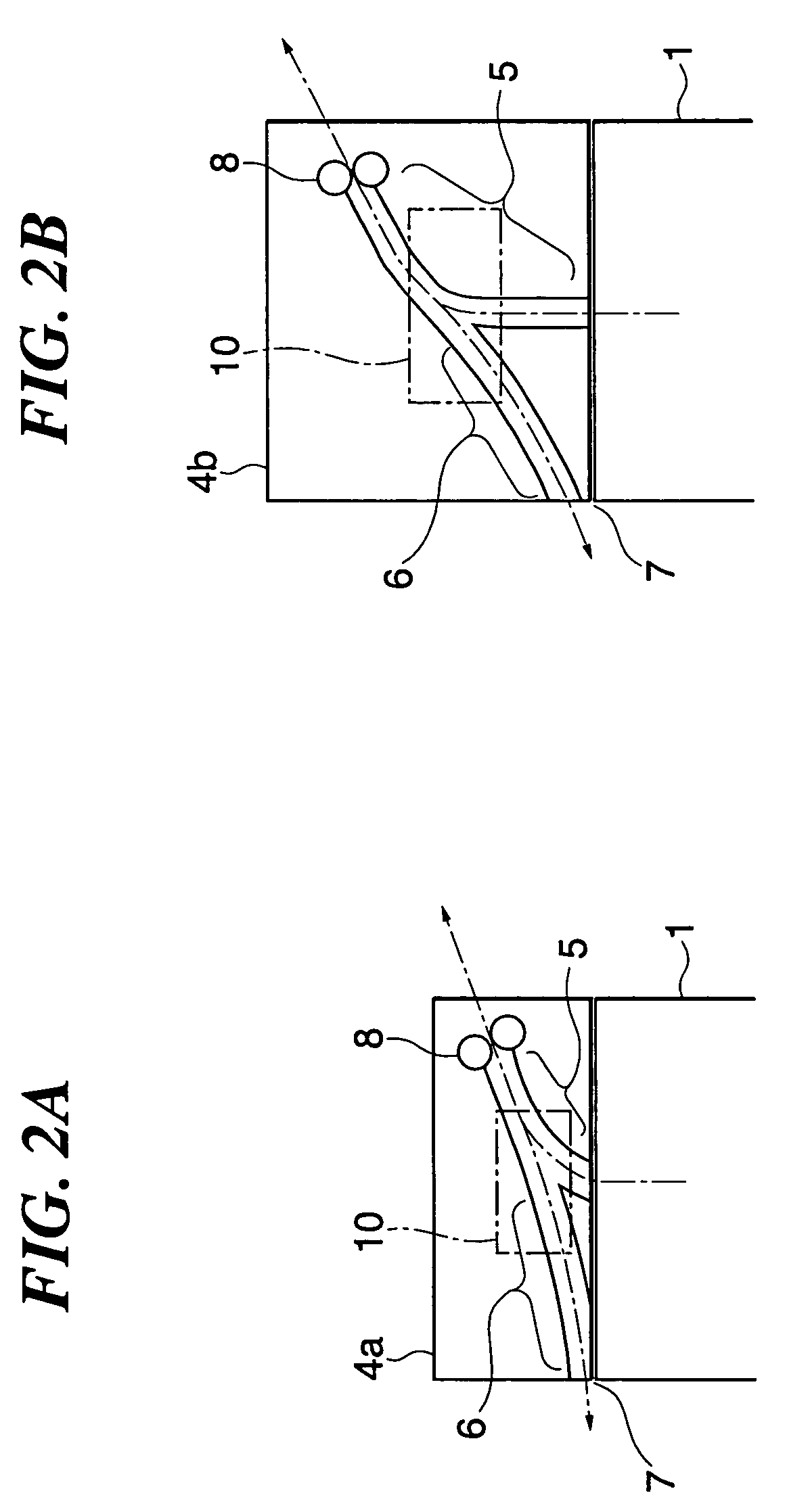
The present invention provides a sheet discharge device that can use a common external unit among multiple sheet discharge units with different specifications. The device includes a unit receiving section where the sheet discharge units can be attached and detached. The sheet discharge units have a normal discharge path and a reverse discharge path that communicates with a sheet transport path of an external unit. The discharge port of the reverse discharge path is set to the same position in all the sheet discharge units, allowing for easy connection with an external unit. The sheet discharge device can be incorporated into a processing device body or can be added as a separate component. The invention also includes a sheet stacking device disposed at the upper section of the processing device body, which can be constituted of an upper cover or a separate tray member. The sheet discharge unit can have a different specification, and a switching mechanism can be utilized in the sheet discharge unit. The invention provides a sheet discharge device that allows for easy connection with an external unit and efficient use of space in the processing device body.

Problems solved by technology

However, the sheet discharging position to the discharge tray is fixed to only one position in this type of the sheet discharge device, whereby the accommodatable number of the discharge sheet of the discharge tray is inevitably limited.
Therefore, it is difficult for a user to change the accommodatable number of the discharge sheet.
Therefore, the conventional technique has a technical problem that, if the user demands to remarkably increase the accommodatable number of sheets, an add-on large-capacity sheet stacking device has to be additionally mounted or the image forming device itself has to be changed to the type of large-capacity model.
Further, in order to add a duplex unit for performing a duplex recording to a sheet as an external unit, the sheet is required to be discharged in a direction different from the direction toward the discharge tray (normally, in the direction reverse to the direction toward the discharge tray), thereby entailing a technical problem that the external unit is required to have a different specification in the sheet discharge unit having a different specification.
However, in this embodiment, a separate adapter is required every specification, thereby causing a fear that the construction of the device is likely to be complicated.

Method used


Image

  • Sheet discharge device and sheet processing device using the same
  • Sheet discharge device and sheet processing device using the same
  • Sheet discharge device and sheet processing device using the same

Examples


embodiment 1

[0062]FIG. 3 is an explanatory view showing an overall construction of a sheet processing device (image forming device in this embodiment) to which the present invention is adopted according to the embodiment 1.

[0063]In the same figure, the image forming device has an imaging engine 21 mounted in a device body 20 (corresponding to the processing device body). Sheet feeding devices 22, 23 of a predetermined number (two-stage construction in this embodiment) are disposed below the imaging engine 21 and a sheet transport path 25 extending in an approximately vertical direction from sheet feeding devices 22, 23 is provided toward a discharge tray 24 at the upper section of the device body 20.

[0064]In this embodiment, the imaging engine 21 adopts the one using an electrophotographic system, and is provided with a photoreceptor drum 31, a charging device (e.g., charging roller) 32 for charging this photoreceptor drum 31, an optical unit (e.g., laser scanning device) 33 for writing a laten...

embodiment 2

[0091]FIG. 9 is an explanatory view showing a sheet processing device (image forming device in this embodiment) to which the present invention is adopted according to the embodiment 2.

[0092]In this figure, the basic construction of the image forming device is approximately the same as that in the embodiment 1, but the construction around the sheet discharge unit is different from that in the embodiment 1. The same components as the embodiment 1 are given by the same numerals for omitting detailed explanation thereof.

[0093]In this embodiment, a sheet discharge unit 201 is exchanged with the sheet discharge unit 61 (having the construction of being capable of discharging a sheet in two directions) used in the embodiment 1. Examples of the sheet discharge unit 201 include a sheet discharge unit with various specifications wherein a discharge position of the sheet is varied according to the accommodatable number of discharge sheet of the discharge tray 24 or a sheet discharge unit 201 w...

embodiment 3

[0143]FIG. 16 is a perspective view of a sheet processing device (an image forming device having an external unit attached thereto in this embodiment) to which the present invention is applied according to the embodiment 3.

[0144]In the same figure, the basic construction of the image forming device is approximately the same as that of the embodiment 1. The different points from the embodiment 1 are that a sorter 250 is applied, as a post-processing device, to the discharge port 270 of the reverse discharge path in the sheet discharge unit 61 and that an image reading device 260 is mounted to the device body 20.

[0145]In the same figure, a main body 251 of the sorter 250 is mounted on a frame 252, while a main body 261 of the image reading device 260 is mounted on a frame 262.

[0146]The discharge port 270 of the reverse discharge path in the device body 20 is positioned at the same position of a paper feeding port (not shown) of the sorter 250, thereby providing no problem in the sheet...


PUM


Abstract

The present invention can easily change an accommodatable number of discharge sheet. Further, the present invention provides a sheet processing device that can easily change the accommodatable number of discharge sheet while aiming to miniaturize the device itself. The present invention provides a sheet discharge device that is incorporated as a part of a processing device body and discharges a sheet processed at a processing section in the processing device body toward a sheet stacking section disposed at an upper section of the processing device body, the sheet discharge device having a unit receiving section formed at the processing device body, wherein plural sheet discharge units each having a different specification can be attached to the unit receiving section. Further, the present invention includes a sheet processing device using the same.

Description

BACKGROUND OF THE INVENTION[0001]1. Field of the Invention[0002]The present invention relates to a sheet discharge device incorporated in a sheet processing device such as copying machine and printer as a part of the body of the processing device, and more particularly to an improvement of a sheet discharge device capable of commonizing an external unit such as a duplex unit and a sheet processing device using the same.[0003]2. Description of the Prior Arts[0004]An image forming device will be taken as an example of this type of a sheet discharge device. There has been conventionally known the one having an imaging engine including, for example, a photoreceptor drum and the like mounted in a body of an image forming device (body of a processing device) and provided with a sheet feeding device and a discharge tray in the body of the processing device, wherein a sheet transport path from the sheet feeding device to the discharge tray is formed at the imaging engine. In this device, an...

Claims


Application Information

Patent Timeline
Patent Type & Authority Patents(United States)
IPC IPC(8): B65H39/10B65H29/58B65H29/60G03G15/00
CPCB65H29/60G03G15/6573G03G2215/00438G03G2215/00421
Inventor SAITO, MANABUKANAI, KENJI
Owner FUJIFILM BUSINESS INNOVATION CORP
Learn More