Centrifugal channel device
a centrifugal microfluidic device and channel technology, applied in the field of channel devices, can solve the problems of limited commercial application of centrifugal microfluidic devices, difficult to deal with a large number of samples and detect, and limited sample volume, so as to facilitate the handling of plenty of samples and avoid contamination
- Summary
- Abstract
- Description
- Claims
- Application Information
AI Technical Summary
Benefits of technology
Problems solved by technology
Method used
Image
Examples
first embodiment
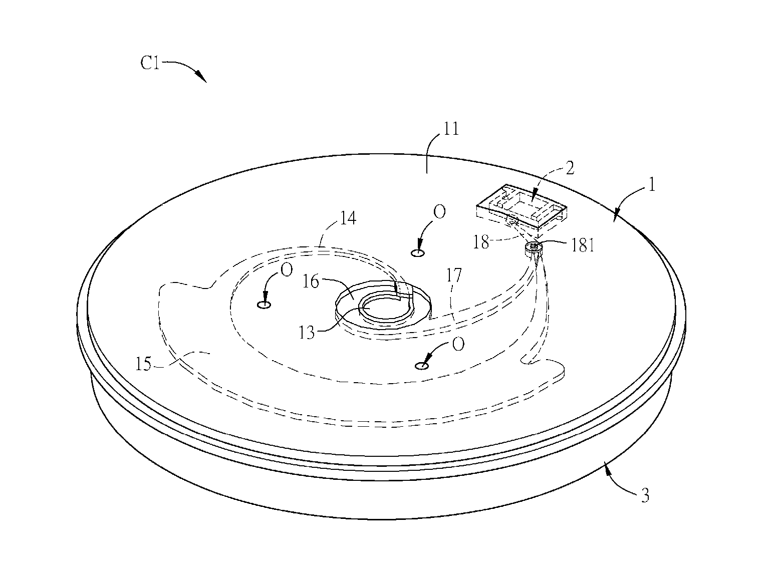
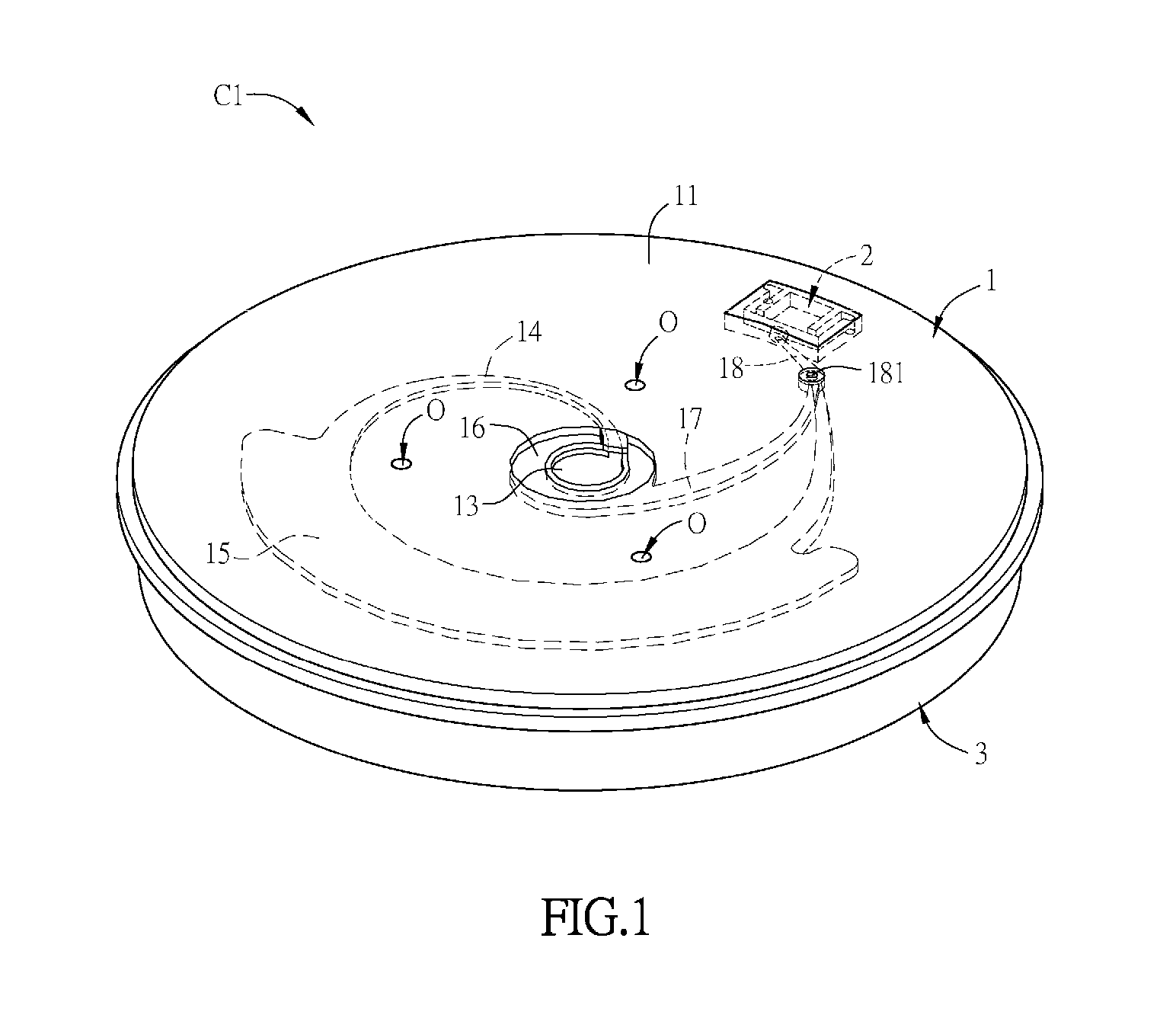
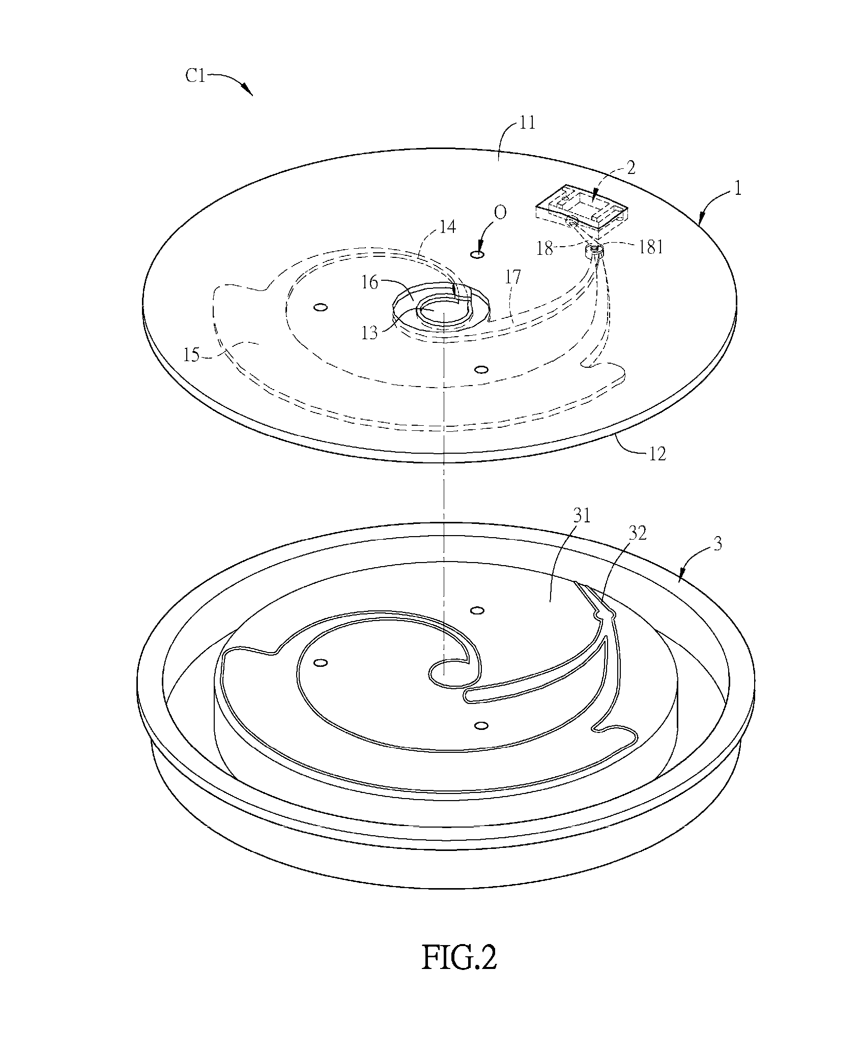
[0055]FIG. 1 is a schematic view of a centrifugal channel device according to the present invention. Refer to FIG. 1, a centrifugal channel device C1 of the embodiment can be applied to deal with different types of samples, and the samples are fluid samples. The sample can be blood samples, biological fluids like plasma fluid, urine or other body fluids and so on. Additionally, the centrifugal channel device C1 of the embodiment can be applied to detect the sample with a low concentration target (specific biomolecule or substance). It means that there are a few content of detection targets in the sample. Thus, it is necessary to inject a lot of samples to obtain a sufficient quantity of detection targets. The centrifugal channel device C1 of the embodiment can be applied to dealing with a large number of samples.
[0056]For instance, in the process of Tumor Metastasis, the tumor cells from the primary site are transferred to other parts of the body far away from the primary site (e.g....
seventh embodiment
[0077]FIG. 10A is a schematic view of a centrifugal channel device according to the present invention. FIG. 10B is a top view of the centrifugal channel device in FIG. 10A. A sample inlet 13f, a sample channel 14f, an isolation tank 15f, a reagent inlet 16f, a reagent channel 17f and a mixing channel 18f are disposed in the channel body 1f. A collecting unit 2f is disposed at a peripheral edge of the channel body 1f. A waste liquid tank 3f is detachably disposed in the channel body 1f. In the embodiment, the channel body 1f is stacked by two disc-shaped plastic sheets. An upper plastic sheet is called “first channel body M1”, and the lower plastic sheet is called “second channel body M2”. The above channels and the inlets can be disposed in the first channel body M1. The lower plastic sheet directly covers on the bottom of the second channel body M2 (referring to FIG. 11A).
[0078]FIG. 11A is a cross-sectional view taken along line A-A of the centrifugal channel device of FIG. 10A. FI...
eighth embodiment
[0085]Referring to FIG. 14A and FIG. 14B, FIG. 14A and FIG. 14B are schematic views of a centrifugal channel device according to the present invention. The centrifugal channel device C8 includes a channel body 1g, a collecting unit 2g and a waste liquid tank 3h. The channel body 1g is disposed at an accommodation space P of the waste liquid tank 3h for accommodating the channel body 1g. The channel body 1g is disk-shaped with enough thickness so the sample channel, the isolation tank, the reagent channel and the mixing channel can form within the channel body 1g. Because these channels and tank is similar to or the same with those described in the previous embodiments, they are not repeated here. The sample inlet 13g and the reagent inlet 16g are located on the first surface 11 of the channel body 1g.
[0086]During disposition, the channel body 1g (disk) is slantingly inserted to the accommodation space P of the waste liquid tank 3h, and then it is disposed at the waste liquid tank 3...
PUM
 Abstract
Description
Claims
Application Information
 - R&D
- Intellectual Property
- Life Sciences
- Materials
- Tech Scout
- Unparalleled Data Quality
- Higher Quality Content
- 60% Fewer Hallucinations
Browse by: Latest US Patents, China's latest patents, Technical Efficacy Thesaurus, Application Domain, Technology Topic, Popular Technical Reports.
© 2025 PatSnap. All rights reserved.Legal|Privacy policy|Modern Slavery Act Transparency Statement|Sitemap|About US| Contact US: help@patsnap.com


