
Collapsible support structure

a support structure and collapsible technology, applied in the direction of machine supports, folding cycles, carts/perambulators with multiple axes, etc., can solve the problems of inherently unstable instability and general lack of stability of tables or carts, and achieve the effect of improving stability and strength

Inactive Publication Date: 2006-06-06
MILLER MARK E +1
View PDF6 Cites 74 Cited by
  • Summary
  • Abstract
  • Description
  • Claims
  • Application Information

AI Technical Summary

Benefits of technology

[0008]The frame members may be four sided in shape overlaying each other and in that case, there are two pairs of leg members, one pair scissors on one side and the other on the opposite side of the frame members and a rigid cross member extends between the two connection members to provide lateral stability.
[0012]Accordingly, it is a principal object of the invention to provide a versatile, collapsible support structure having greatly improved stability and strength in the raised position for holding heavy or bulky objects, and when mounted on wheels, provide mobility without losing stability with the load in a raised position.
[0015]Another object is to provide a collapsible support structure that is smooth to operate and can be raised to considerable heights without losing its stability, and yet collapsed to a very compact size.

Problems solved by technology

These tables or carts generally lack stability when they are designed to move, i.e., mounted on wheels, or are traveled over uneven ground.
And in trying to achieve support heights of thirty or more inches, with heavy or bulky loads, they are inherently unstable because of the additional factor of the load's center of gravity being in an elevated position.

Method used


Image

  • Collapsible support structure
  • Collapsible support structure
  • Collapsible support structure

Examples


Embodiment Construction

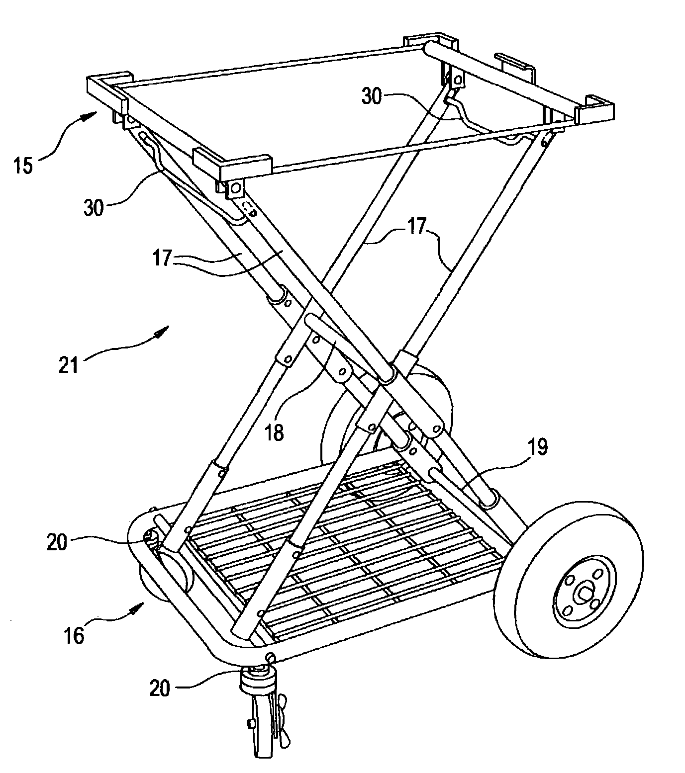
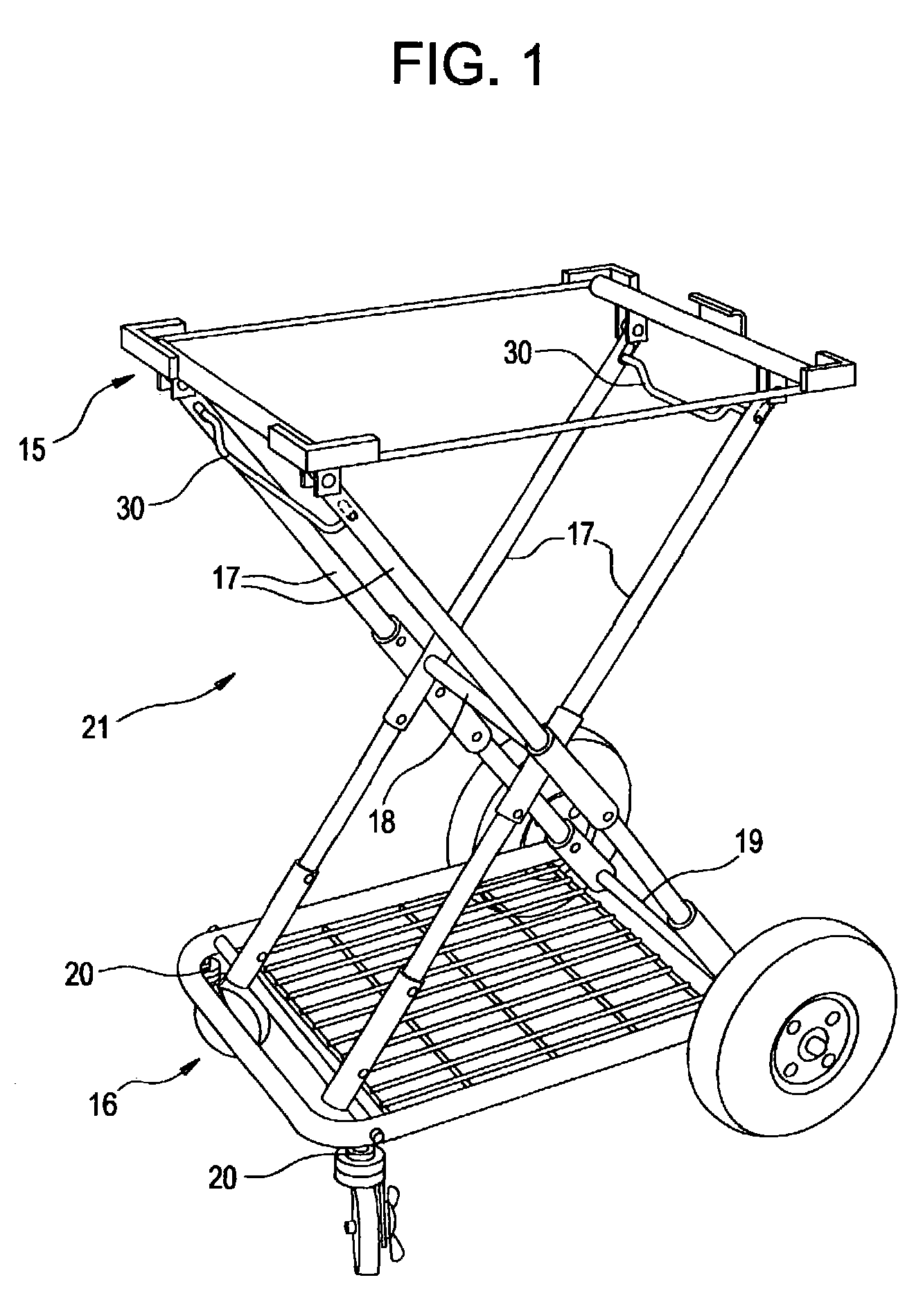
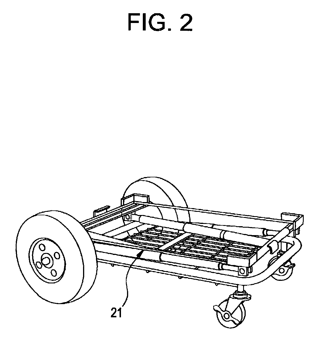
[0029]Referring to FIGS. 1 and 2, a collapsible support structure (21), according to a preferred embodiment of the invention, is associated with a hand cart having an upper rectangular frame (15) adaptable for carrying a bulky load, like a monitor or oscilloscope (not shown). This frame is directly above a bottom rectangular frame (16) of similar size and shape. The two frames are roughly seventeen by twenty two inches. The bottom frame is adaptable for carrying separate, usually related heavy items to those on the upper frame, such as a computer, and possibly a DC battery power source (also not shown).

[0030]The bottom frame (16) has a horizontal axle (19) on one end. It rotatably supports a pair of ground engaging wheels, approximately ten inches in diameter. On the other end, a pair of smaller caster wheels are mounted. They are approximately four inches in diameter. They can swivel on vertical axles (20) and also rotate providing a turning capability to the cart since the larger ...


PUM


Abstract

A collapsible support structure has pairs of leg members (17) pivotally joined intermediate their length in crossed fashion by a connection member (18) that is capable of sliding longitudinally with the pivotal joint as the leg members extend in a scissors—like manner to support an object.

Description

CROSS REFERENCE TO RELATED APPLICATIONS[0001]This application is related to a U.S. Provisional Application, Ser. No. 60 / 402,460 filed Aug. 9, 2002. It has the same title and is by the same inventors as this application and is fully incorporated herein by reference as to the common subject matter for which this application relies on for priority of invention.BACKGROUND OF INVENTION[0002]The present application was funded in part by the Kentucky Science and Technology Corporation [KSTC], a Commonwealth of Kentucky business development entity located in Lexington, providing funding for developments in the Blue Grass region of Kentucky. The KSTC provides grants and early phase investment capital for business development and innovations in cooperation with the State Economic Development Cabinet. This invention was evaluated by KSTC staff members and deemed to merit grant funding. Although neither KSTC nor the Commonwealth of Kentucky acquired any right, title or interest, or license, exp...

Claims


Application Information

Patent Timeline
Patent Type & Authority Patents(United States)
IPC IPC(8): B62B1/00B62B3/02
CPCB62B3/022B62B2205/20B62B2205/06
Inventor MILLER, MARK E.MILLER, JOSEPH C.
Owner MILLER MARK E
Learn More