

Fluidically isolated pumping and metered fluid delivery system and methods
a fluid delivery system and fluid technology, applied in the field of microfluidics, micropumping, precise fluid dispensing, can solve the problems of blood analysis being contaminated with remnants, fluid flowing through the device contaminating all the moving parts of the device, and avoiding damage to fragile blood cells
- Summary
- Abstract
- Description
- Claims
- Application Information
AI Technical Summary
Benefits of technology
Problems solved by technology
Method used
Image

Examples
Embodiment Construction
[0001]1. Field of the Invention
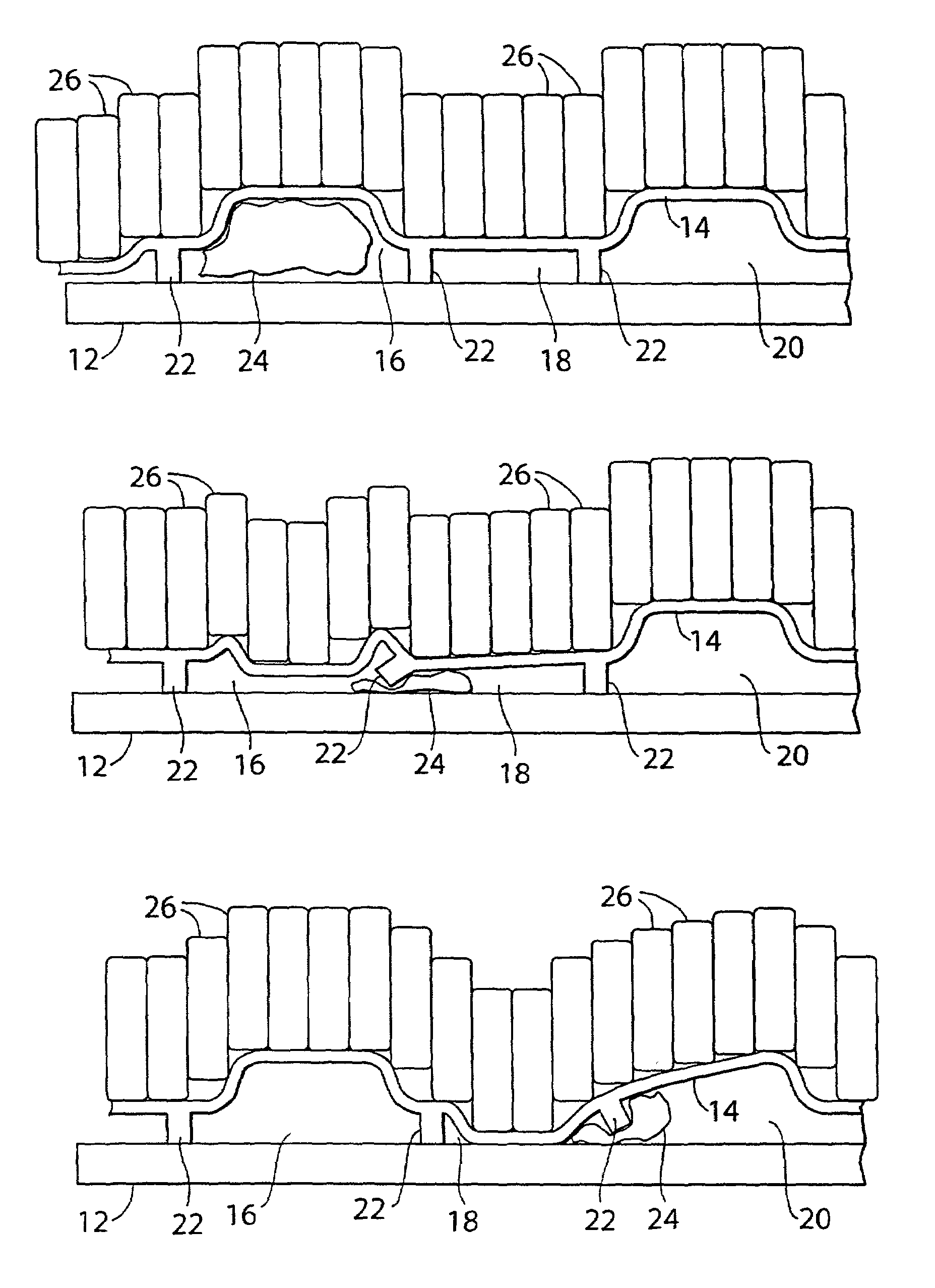
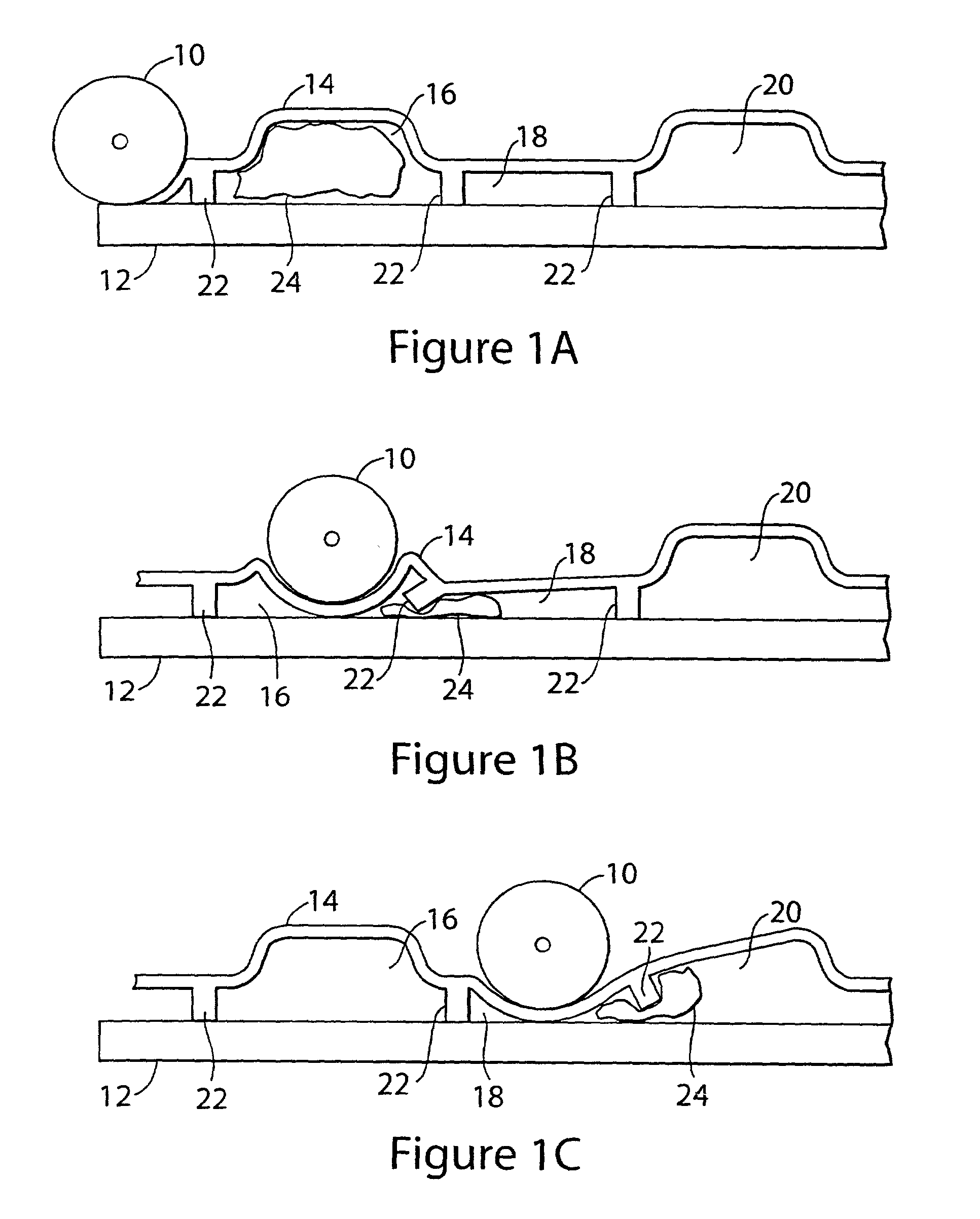
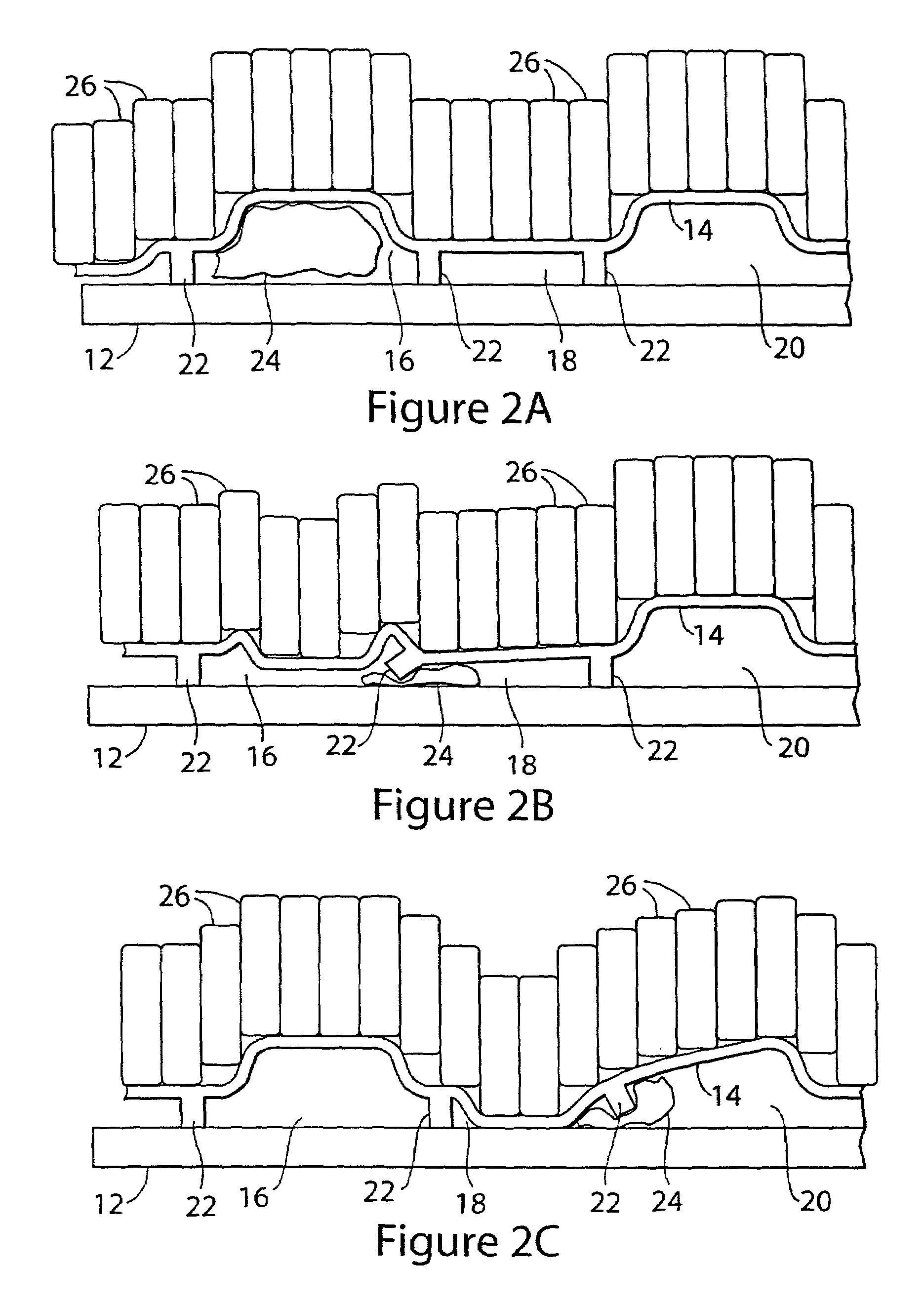
[0002]The present invention is related to micro-fluidics, micro-pumping, and precise fluid dispensing. More particularly, the invention relates to devices and methods for microscopic pumping of blood and reagents.
[0003]2. Background of the Invention
[0004]Micro pumping for transporting small volumes of fluids is made possible by micro pumps which use piezoelectric, surface wave, thermal, fluidic or static electric actuation to move diaphragms or paddle wheels. An example of a paddle wheel type pump is described in application Ser. No. 09 / 976,991, Inventor: Paul Lum, entitled “A MICRO PADDLE WHEEL PUMP FOR PRECISE PUMPING, MIXING, DISPENSING, AND VALVING OF BLOOD AND REAGENTS”).
[0005]These devices work in a manner similar to conventional pumps but operate on a microscopic scale. Paddle wheels operate similarly to impellers in centrifugal pumps. The impeller consists of a number of blades, either open or shrouded, mounted on a shaft that projects outside ...
PUM
| Property | Measurement | Unit |
|---|---|---|
| volumes | aaaaa | aaaaa |
| volumes | aaaaa | aaaaa |
| compressive force | aaaaa | aaaaa |
Abstract
Description
Claims
Application Information